---
title: "Mechanic LS720 Ring Lamp"
subtitle: "Is it any good for photography?"
author: "Pedro J. Aphalo"
date: "2025-03-06"
date-modified: "2026-06-07"
toc: true
categories: [equipment, illumination]
keywords: [LED light, comparison]
format:
html:
code-fold: true
code-tools: true
lightbox: auto
license: "CC BY-SA"
draft: false
abstract: |
I review the Mechanic LS720 Polarization Ring Lamp designed for use in electronics repairs as a possible light source for use in close-up and macro photography. I used an OM-System OM-1 digital camera and three M.Zuiko macro lenses for the tests. I conclude that the ring light is useful in spite of some limitations, including low CRI, blue-shifted CCT, and PWM dimming. I also show how to reduce glare with a mask.
---
{{< include /_includes/folded-code-tip.qmd >}}
```{r, message=FALSE}
library(ggplot2)
library(photobiology)
library(ggspectra)
library(photobiologyWavebands)
library(photobiologyLamps)
library(photobiologyFilters)
library(photobiologyInOut)
library(patchwork)

theme_set(theme_minimal(14) +
            theme(plot.title = element_text(size = rel(1))))
```
## Introduction
Ring lights are useful in macro photography and micro photography when even illumination is desired, as there is usually limited room for placing other types of LED lamps or flashes [@Blaker1978;@Durand1977]. Alternatively small light tents can be used [@Blaker1978;@Durand1977]. When photographing some types of objects such as electronic circuits or biological samples in water, reflections can be difficult to control by changing the light source position. A traditional approach to control reflections is the use of polariser filters. These are effective only when the incident light is polarised, like sunlight. In the case of artificial light sources, for effective control of reflections polariser filters have to be used both on the lens and on the light source at different rotation angles [@Blaker1978].
Ring lights provide shadowless illumination at close distances and macro photography. Some ring lights are relatively large and used for portrait photography and video. For macro photography small ring lights (earlier xenon flashes and more recently LED-based) are rather frequently used. With the now widespread use of digital-camera-based macroscopes for electronics assembly and repair, low-priced ring lights have become available. The small size of LEDs has made possible the design of light-weight small-sized ring lights with polarisers to control reflections. One example is the _LS720 Polarization Ring Lamp_ from Mechanic which I recently bought ([@fig-ls720]). I bought the black version; a blue version is also available.
::: {#fig-ls720 layout="[[1,1], [1]]"}
{#fig-ls720-box-front}
{#fig-ls720-box-botom}
{#fig-ls720-front}
Mechanic LS720 ring light with double polarisers and the box it arrived in. The bottom of the box contains the manufacturer's description.
:::
The [Mechanic](https://www.mechanichk.com/) LED-based _LS720 Polarization Ring Lamp_ is sold as a light source for "microscopes" used in the repair of electronic circuits such as those in mobile phones ([@fig-ls720-box-front]). An important issue when working with such circuits are reflections from metal such as solder and copper traces and from the plastic in which some components are encapsulated. This ring light, as well as some other competing ones, has two circular polarisers, a fixed one located at the back of the ring light, i.e., in front of the camera lens, and a ring-shaped one in front of the LEDs that can be rotated ([@fig-ls720-front]). By rotating the ring-shaped polariser so that the polarization planes are at $90^\circ$ it is possible to very effectively control specular reflections. Thus, the image is captured through the polariser at the back of the ring light and through the hole in the front one. The light from the LEDs is filtered on its way out by the ring-shaped filter. Two features of the LS720 seemed to me preferable to those offered by other ring lights at similar prices. The filters are described as multi-coated (MC) using a multi-layer nano coating ([@fig-ls720-box-botom, however, see below]). The dimmer is not built into the ring light but instead in a cable connected to the ring lamp via an USB-C socket ([@fig-ls720-box-front]).
Being the intended use at high magnification, the area illuminated is relatively small. This is achieved by positioning the LEDs at an angle pointing inwards with those in the two rings at different angles ($25^\circ$ and $25^\circ$). There are 72 LEDs in "traditional" $5\,\mathrm{mm}$ "thru-hole" packages arranged in two concentric rings. The LED (electric) power rating is 7.2 W. The dimmer output is rated at $5\,\mathrm{V} \times 2\,\mathrm{A} = 10\,\mathrm{W}$. Anyway, as the illuminated area is a small circle, the power is more than enough. Colour temperature (CCT) is rated as $10\,000\,K$ to $12\,000\,K$ and no CRI rating is reported. The dimmer allows fine grained control of the light output, apparently using pulse width modulation (see page [PWM dimming and digital photography](PWM-banding-readout.qmd)). The body of the ring light is made of metal with a black finish both outside and inside. With a diameter of $77\,\mathrm{mm}$ and a depth of $30\,\mathrm{mm}$, it is small. At $159\,\mathrm{g}$ the LS720 ring light is not heavy.
Model LS720 has an M48 thread at its back, and is the version I have bought. There is also model LS720+ which seems nearly identical, except that it uses a different type of ring light-to-lens mechanical connection, based on a grooved ring on the lens and three set screws on the ring light. As $48\,\mathrm{mm}$ to $52\,\mathrm{mm}$ step rings are readily available, I opted for the LS720 to ensure easier mounting and consistent alignment. The $48\,\mathrm{mm}$ thread and 45 mm opening at the back are not a constraint on the lens acceptance angle, as the effective constraint is that by the $45\,\mathrm{mm}$ diameter of the opening in the polariser at the front of the ring light.
My aim here is to test how useful this ring light is for macro photography, which is **not** the use it is sold for (several reviews considering its intended use are available in the internet). The main things I consider are the spectral quality of the light, the frequency used for PWM dimming and the uniformity and size of the illuminated circle at different distances. The working distance depends on focal length and magnification. Thus, it can be expected that at some working distances and focal lengths the light field will be uneven or of the wrong size.
## First impressions
The metal body is lightweight but seems strong. The black surface finish is tidy and the lettering is printed or painted. Looking at how they reflect light, neither of the two polarizer filters seems to be anti-reflection coated in spite of the description in the packaging and "MC" labelling on the filter ring. This is not what I expected! Glare and loss of contrast seems to be a problem that increases as the distance between the ring light and the subject increases. In addition at more than approximately 15 cm distance the light field starts to become uneven. At short distances problems are fewer. With long focal length lenses used at moderate magnification, adding a spacer between the ring light and the lens front could be useful as lowering the ring light with respect to the lens front makes the illuminated area smaller and brighter.
There are some shiny black surfaces on the inside of the ring light and some wires with white insulation. The diameter of the polariser filter at the back of the ring light is larger than necessary and a smaller one or a black mask could help decrease the reflections. I cannot see how to disassemble the ring light to remove the polariser at its back and replace it with smaller one with good anti-reflection coatings. Adding a mask on the existing filter seems easier, even if not ideal.
The camera live view display shows erratic banding when dimming, most likely due to PWM dimming. At full power I did not notice such problems. The ring lamp has a USB-C connector to the cable from the dimmer. At least in principle, the PWM dimmer could be replaced with a constant current (CC) dimmer.
The rotating circular polariser at the front, moves freely. Some damping to avoid accidental rotation and allow precise settings would have been nice.
The ring light gets warm during use, but at least in short use sessions, not excesivelly. The back of the dimmer gets hot to the touch. The dimmer seems prone to occasionally switch on by itself, possibly due to line noise from the power supply. This suggests that the dimmer is poorly designed or that quality control has failed for the unit that was delivered to me.
All-in-all the ring light seems o.k. for its price of less than 30 € (direct from China, or about 50 € from European suppliers). Good polariser filters for photography cost more than this (The cheapest filters 48 mm and 72 mm in diameter from Hoya sell for about 30 € and 45 €, respectively). I would be willing to pay more for a similar ring light without the weaknesses of the LS720.
At this point I think the ring light will be useful for macro photography and close-up photography. I expect that some customization will be needed to control reflections. Internal reflections are also a problem with most macro extension tubes and lens adapters sold at AliExpress (see page [Macro Extension Tubes—Internal Reflections](../lens-adapters/macro-tubes-glare.qmd) at this site). Only high-end third party and original camera manufacturers' lens attachments control reflections well.
## Attachment to lenses
I use an OM-1 digital camera and macro lenses from [OM-System](https://www.omsystem.com/) (formerly Olympus camera division). I have been using _Manfrotto Xume quick release adapters_ with my 52 mm filters and they have enough pull to hold the ring light when used in a copy stand and with care ([@fig-MZ60; @fig-MZ90]). Using this approach is convenient but adds 10 mm between the lens front and the back of the ring light ([@fig-MZ60-detail; @fig-MZ90-detail]), and care is needed so that the ring light remain in place. The additional 10 mm are not a problem with the M.Zuiko 60 mm 1:2.8 Macro lens or with the M.Zuiko 90 mm 1:3.5 Macro lens. As both lenses have an internal focusing mechanism, the ring light attached in this way does not disturb their use. Alternatively, the ring light could be screwed with adapter rings to the filter thread at the front of the lenses. Importantly, both lenses leave enough working distance to reach their maximum magnification with the ring light attached. This is important as ring lights are most needed at high magnifications.
::: {#fig-mz60 layout-ncol=2}
{#fig-MZ60}
{#fig-MZ90}
{#fig-MZ60-detail}
{#fig-MZ90-detail}
LS720 ring light on M.Zuiko 60 mm f 2.8 Macro and M.Zuiko 90 mm f 3.5 Macro Pro lenses.
:::
The LS720 ring light can be used effectively with the 90 mm lens at $\times 2$ to $\times 0.5$ magnification, with moderate vignetting within $\pm 1$ EV and very effective control of reflections. At $\times 0.25$ magnification unfiltered light reaches the subject area and control of reflections is lost, however, illumination remains usable with non-reflective subjects. The ring light can be used with 90 mm lens plus the MC-20 2x teleconverter up to $\times 4$ magnification.
The 60 mm lens can be used without problems from $\times 1$ to $\times 0.25$ with good control of reflections, but with less working space than the 90 mm lens.
In contrast, the M.Zuiko 30 mm 1:3.5 Macro is too wide to be used effectively. At low magnifications the illuminated area is too small and at high magnification non-polarised light illuminates the centre of the image and reflections are not controlled ([@fig-mz30]).
::: {#fig-mz30 layout-ncol=1}
 {width=50%}
Unevenly illuminated field of view when using the N.Zuiko 30 mm f 3.5 Macro lens with the LS720 ring light.
:::
::: callout-tip
# Adding a black mask
Adding a lens shade to the front of the ring light is not possible because of the lack of space at high magnifications. An alternative approach to reduce the angle of acceptance is to use a _black_ mask to decrease the diameter of the opening at the back of the ring light ([@fig-ls720-mask]).
::: {#fig-ls720-mask layout-ncol=2}
{#fig-ls720-no-mask}
{#fig-ls720-with-mask}
LS720 ring light. Lens-side view, with and without the black flock mask in place. The mask blocks the direct and in part reflected light from the ring lights' LEDs from reaching the front element of the lens.
:::
My first quick test was to use a ring of black paper as a mask. This mask controlled the glare rather well but is unlikely to last for long in use. A more durable approach is to stick a circle of black flocking. I used [_ARAX Optical Photo Sticky Flocking Sheet_](https://araxfoto.com/accessories/flock/) 0.35 mm-thick (98% absorptance) from [AraxFoto](https://araxfoto.com/). I cut the self-stick flocking with "leather" punches 45 mm and 25 mm in diameter, and placed one ring on the back of the filter using tweezers. I added a second flocking ring on the inner side of the filter, cutting it in two halves to make installation with tweezers easier.
If you use a different lens, a 25 mm opening could be too small. It is easy to find the smallest diameter opening that does not introduce vignetting with loose rings of thick black paper. Vignetting needs to be assessed at the different magnifications that will be used. Only stick the flocking after a suitable size has been determined. The outer diameter of 45 mm is given by the size of the ring light. The opening diameter of 25 mm works with the objectives I intend to use. Leather punches are readily available in diameters that increase in steps of 5 mm.
:::
## Light spectrum
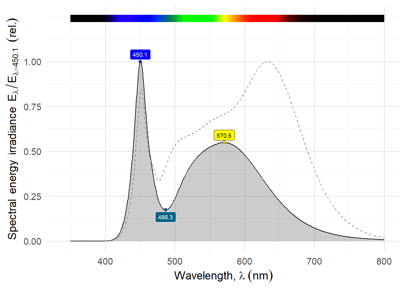
The ring light emits very little red light compared to green and blue compared to a LED fill-light ([@fig-spectrum]). For the ring light, the auto white balance on the OM-1 digital camera yields a CCT of $\approx 10\,000\,K$ and that from the white-balance picker in Capture One is only very slightly lower. The CCT computed from the measured emission spectrum is higher at $\approx 13\,500\,K$. A mismatch is not surprising as camera sensors have only RGB sensor channels while the spectroradiometer used has a wavelength resolution of $\approx 1\,\mathrm{nm}. The green-magenta corrections computed in camera and by Capture One are small values. Thus the light spectrum is shifted strongly towards blue, with a very small green cast. By sight, the two automatic white-balances, in camera and in software, were able to correct for the CCT of the light source. (The effectiveness of white balance algorithms is likely to be camera-specific due to the specific match between Bayer array filters on sensors and light spectrum. The range of accepted values for CCT in camera firmwares and in photo edition software varies, and could potentially cause difficulties.) The Sunwayfoto FL96 fill light is used for comparison, set to a nominal CCT or 4000 K and its CCT computed from the spectrum is 3500.
```{r}
#| label: fig-spectrum
#| fig-cap: Emission spectrum of the LS720 ring light. Peaks and valleys are labelled with their wavelength in nanometres (nm) and colour. The spectrum show was measured with the dimmer set at maximum output, but dimming had minimum effect on the shape of the spectrum. For comparison, the dashed line shows the spectrum of a Sunwayfoto FL96 LED lamp set at a CCT of 4000 K.
load("data/Mechanic_LS720_8cm_max_001.spct.Rda")
rm(Mechanic_LS720_8cm_max_001.raw_mspct)
autoplot(normalise(Mechanic_LS720_8cm_max_001.spct),
         geom = "spct",
         range = c(350, 800), span = 51,
         annotations = c("peak.labels", "valley.labels", "colour.guide")) +
  geom_line(data = trim_wl(lamps.mspct$Sunwayfoto.LED.FL96.at.4000K,
                           range = c(350, 800)),
            colour = "grey50", linetype = "dashed",
            na.rm = TRUE)
```
The colour rendition index (CRI) computed from the emission spectrum is only $\approx 78$, which most likely will degrade colour reproduction. The Sunwayfoto FL96 fill light used for comparison, is rated at CRI 95. Its CRI computed from the spectrum is 96.
Although a higher CRI would have been preferable, this ring light is not intended for photography, and neither the high CCT nor low CRI are unexpected. The spectrum is not ideal for good colour reproduction, but usable. The ring light is unsuitable for use in combination with ambient light, both indoors and outdoors, possibly except with the ring light very near the subject.
::: callout-note
# Correcting CCT
## Filters
A possibility is to correct the cool CCT with a warming filter. I simulated _in silico_ how the spectrum would look if a warming filter from Hoya Tokina would be used. Using a Hoya W12 (120 mired) filter we get CCT = `r round(as.numeric(spct_CCT(Mechanic_LS720_8cm_max_001.spct * filters.mspct$Hoya_W12_HMC)), digits = -1)` K and CRI = `r round(as.numeric(spct_CRI(Mechanic_LS720_8cm_max_001.spct * filters.mspct$Hoya_W12_HMC)))`. In comparasion without a filter we get CCT = `r round(as.numeric(spct_CCT(Mechanic_LS720_8cm_max_001.spct)), digits = -2)` K and CRI = `r round(as.numeric(spct_CRI(Mechanic_LS720_8cm_max_001.spct)))`. Although we get a warmer CCT, CRI does not improve. The low light output in the red remains as a problem.
```{r}
#| label: fig-spectrum-warmed
#| fig-cap: Emission spectrum of the LS720 ring light corrected with a Hoya W12 filters (+120 mired) Umber warming filter. Peaks and valleys are labelled with their wavelength in nanometres (nm) and colour. The LS720 spectrum show was measured with the dimmer set at maximum output. The filter spectrum is from Hoya Tokina's documentation. For comparison, the dashed line shows the spectrum of a Sunwayfoto FL96 LED lamp set at a CCT of 4000 K.
autoplot(normalise(Mechanic_LS720_8cm_max_001.spct * filters.mspct$Hoya_W12_HMC),
         geom = "spct",
         range = c(350, 800), span = 51,
         annotations = c("peak.labels", "valley.labels", "colour.guide")) +
  geom_line(data = trim_wl(lamps.mspct$Sunwayfoto.LED.FL96.at.4000K,
                           range = c(350, 800)),
            colour = "grey50", linetype = "dashed",
            na.rm = TRUE)
```
## Colour Profile
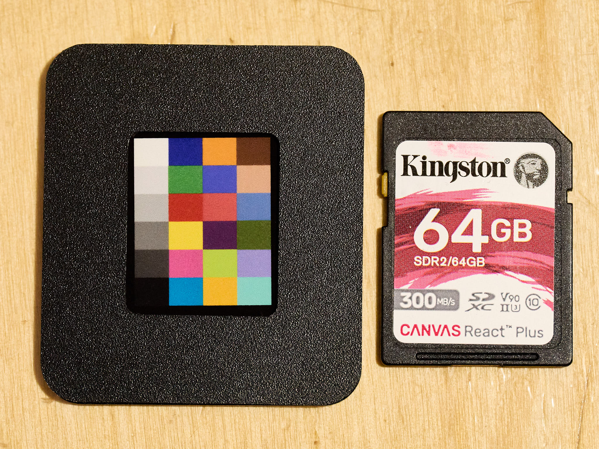
I used a suitably small colour target and special software to construct the profile. I use Capture One, which uses ICC profiles instead of DNG profiles used Adobe software. I have used Lumariver Profile Designed (currently Standard 2.0) for several years. Very small targets are either very expensive from Lumabright (formerly X-Rite) or much cheaper from Charttu in China ($\approx 30$€). The _Charttu 24 ColorChecker Classic Nano_ $40\times 50$mm is of a size is ideal for macro photography and fits the illuminated area from the LS720 (@fig-charttu).
::: {#fig-charttu layout-ncol=1}
{#fig-charttu-1}
{#fig-charttu-2}
{#fig-charttu-3}
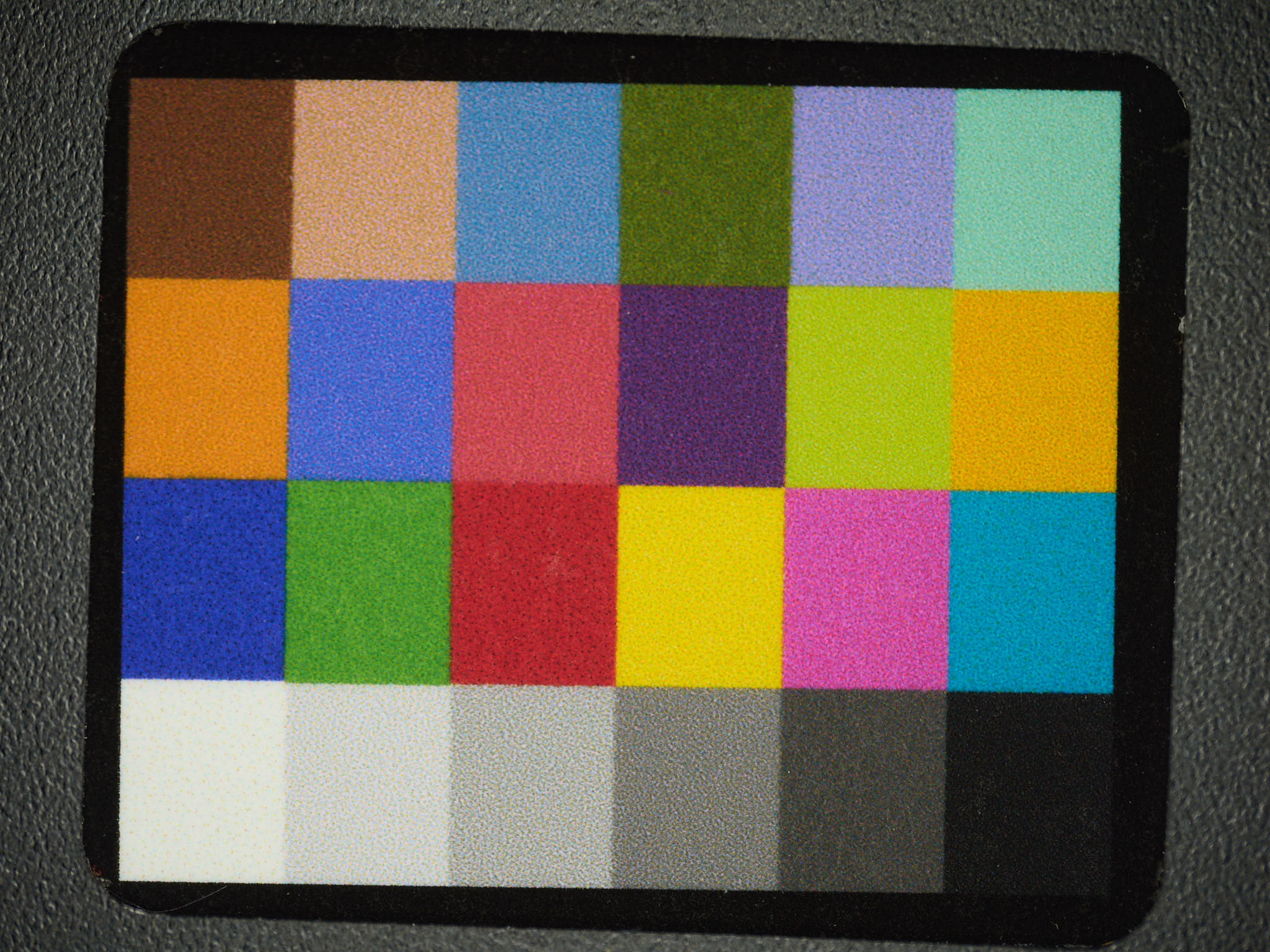
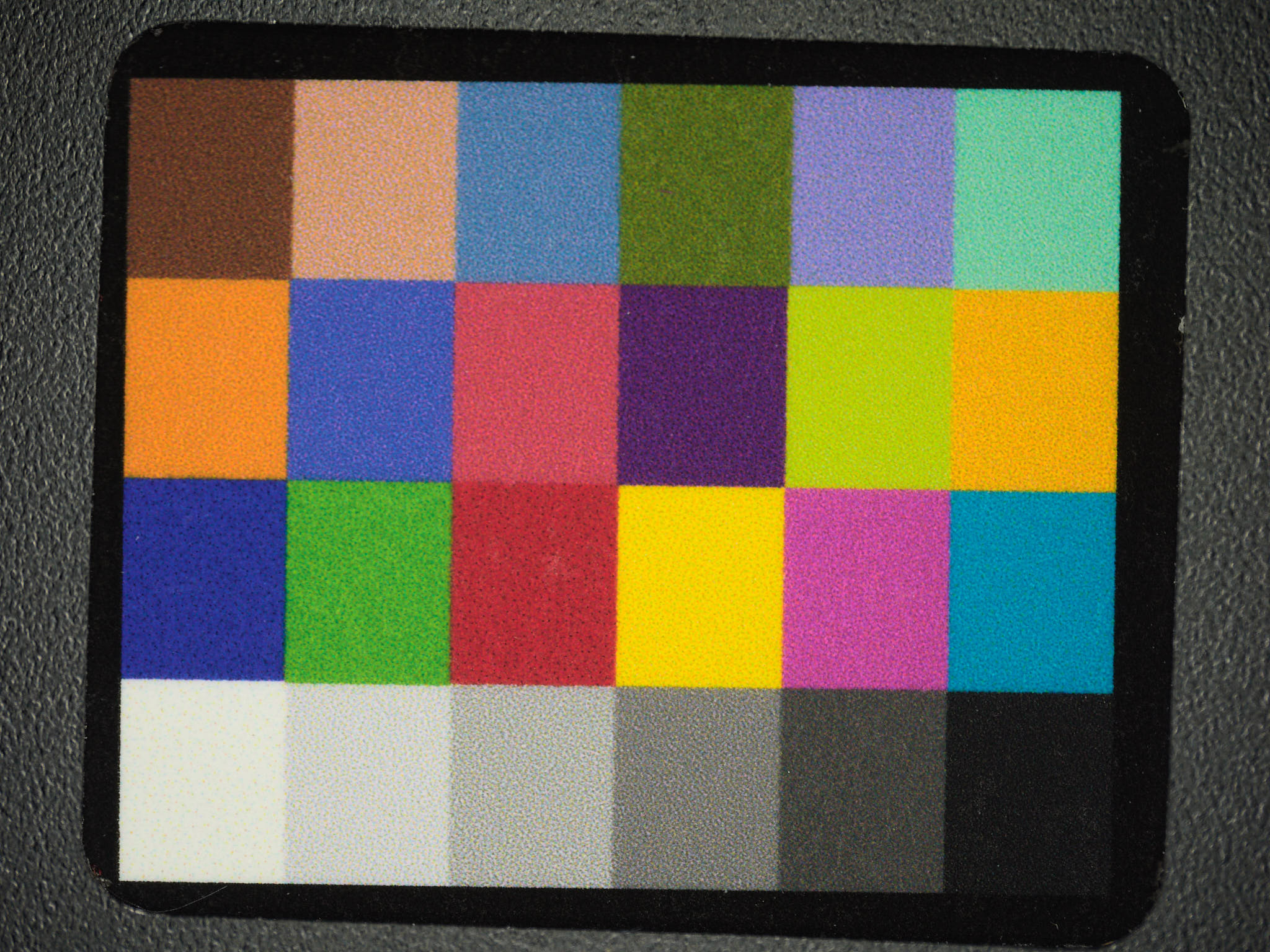
Charttu 24 ColorChecker Classic Nano. The layout of the colour tiles in this colour reference is the same as in the X-Rite ColorChecker 24. The colurs of the tiles according to specifications are very similar, but not identical.
:::
The tiles in Charttu targets aim to approximate those in X-Rite targets (post 2014) but do not have exactly the same spectral reflectance. In Lumariver PD, I used the settings for _X-Rite ColorChecker 24_ to construct an ICC profile with no white balance correction. The profile is good enough for improving the colour rendering, but starting from a low CRI LED source and using approximate target color descriptions does not ensure perfect colour reproduction, only and improved one. By comparing @#fig-charttu-2 and @#fig-charttu-3 we can see darker blues and violet and brighter greens, yellow and reds. The difference is not huge but significant.
:::
## Dimmer and Dimming
The dimmer of the LS720 is in-line in the USB cable, with a USB-C connector to the ring light and a USB type A connector on the power supply side. An USB charger or power bank capable of supplying 5.0 V at 2 A is needed, but not included. Smart phone chargers with a power rating of 10 W or more can be expected to work, but a plug adapter is in some cases needed. In the tests I used a recently bought GaN 45W USB charger from [_hama_](https://www.hama.com/) (00201993 mobile device charger supporting Power-Delivery- and Qualcomm Quick Charge 2.0/3.0 protocols).
The measured electrical power use at the dimmer input with dimming set at maximum output is 7.15 W when using a 45 W USB charger capable of 5.0 V at 3.0 A. This is well within measurement tolerance of the 7.2 W rating advertised. One of my USB testers gave unstable readings when connected to the dimmer and light source, but another one did work well.
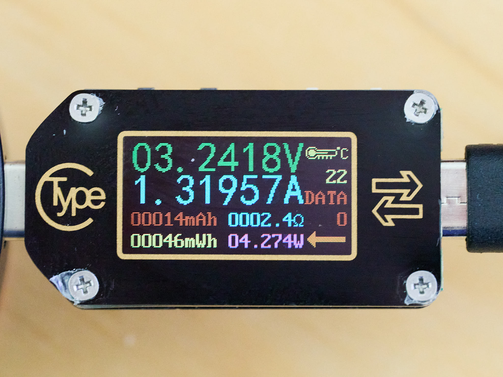
The actual power used to drive the LEDs at maximum output seems to be about 4.0 W (3.2 V at 1.25 A). I used a Rui Deng TC66 USB-C tester ($\approx 30$€ at ALiExpress) inserted between the dimmer and ring light for this measurement. The screen of the meter remained dark with the ring light working normally. This was except at the maximum output setting of the dimmer, as 3.2 V is barely enough for the tester to work. The readings were, thus, suspect.
A USB-C extension power cable inserted between the dimmer and the ring light did work just fine.
Using an oscilloscope, it is possible to measure the frequency, duty cycle and transients, both in the electrical and light outputs. I measured the light output during dimming With a [Pico Technology](https://www.picotech.com/) 2204A oscilloscope connected to a TSL254R analogue light sensor (with $2\,\mathrm{\mu s}$ rise and fall times) powered by $3.3\,\mathrm{V}$ using the PicoScope 7 test and measurement software.
The dimmer relies on pulse width modulation (PWM) using a frequency of $2.49\,\mathrm{kHz}$ (square wave) ([@fig-waveforms-pwm]). Maximum duty cycle is $98.1\%$ and minimum duty cycle is $1.1\%$. The control nob seems to be an encoder but steps are suitably small giving good control. The waveform trace in the oscilloscope shows that the tops of the peaks are not square. This could be either noise from the USB-C charger or from the dimmer circuit. The OM-1 digital camera's live view seems to have difficulty syncing to the pulsing light from this ring light, and this is tyring to one's eyes.
```{r}
#| label: fig-waveforms-pwm
#| fig-asp: 1
#| fig-cap: Measured light output in time at different settings of the dimmer. The dimmer uses pulse width modulcation switching the LEDs on an off every 0.0004 s or 2500 times per second. The yellow peaks show the time when the LEDs are on. The amplitude or maximum output is always the same, and is expressed relative to the maximum. Moderate kernel smoothing was applied. Superimposed on the main square wave waveform there is a higher frequency and small amplitude oscillation of unknown origin.
load("data/LS720-dim-ls.rda")

ggfig <-
  function(d) {
    ggplot(ls720_dim.ls[[d]], aes(x, y/2)) +
      geom_area(fill = "orange", colour = "black", alpha = 0.25) +
      scale_y_continuous(name = "Irradiance (relative)") +
      scale_x_continuous(name = "Time (ms)",
                         breaks = c(-0.4, 0, 0.4, 0.8, 1.2)) +
      labs(title = d)
  }

(ggfig("Dimmed to 10%") +
    ggfig("Dimmed to 25%") +
    ggfig("Dimmed to 50%") +
    ggfig("Dimmed to 75%") +
    ggfig("Dimmed to 90%")) +
  plot_layout(ncol = 2, axes = "collect")
```
At a $2.5\,\mathrm{kHz}$ frequency, one cycle lasts $0.4\,\mathrm{ms}$. Thus when using a mechanical shutter, together with the dimmed ring light, at fast shutter speeds the pulsing introduces banding in the images. I tested by taking photographs at shutter speeds between $1/8000\,\mathrm{s}$ and $1/10\,\mathrm{s}$ with the ring light dimmed to 50% duty cycle ([@fig-ls720-mechanical-shutter]). Shutter speeds of $1/3200\,\mathrm{s}$, $1/1600\,\mathrm{s}$, and $1/800\,\mathrm{s}$ and any slower shutter speeds are not affected by banding. Other shutter speeds faster than $1/800\,\mathrm{s}$ suffer from banding.
::: callout-note
# Anti-Flicker shooting mode
The _anti-Flicker shooting_ of the OM-1 camera can be used only with the mechanical shutter. According to its description, it can increase the lag in the response to the shutter release. The mechanical shutter in the OM-1 supports a maximum shutter speed of 1/8000 s (or $125\,\mathrm{\mu s}$).
**The _anti-Flicker shooting_ mode synchronizes the release of the shutter to the timing of the flicker in the illumination. It can effectively eliminate banding.**
:::
::: {#fig-ls720-mechanical-shutter layout-ncol=3}
{#fig-ls720-m8000}
{#fig-ls720-m6500}
{#fig-ls720-5000}
{#fig-ls720-m4000}
{#fig-ls720-m3200}
{#fig-ls720-m2500}
{#fig-ls720-m2000}
{#fig-ls720-m1600}
{#fig-ls720-m1250}
Examples of banding caused by PWM dimming when using the mechanical shutter in the OM-1 digital camera with the M.Zuiko 90 mm 1:3.5 Macro lens. The SD card was illuminated with the Mechanic LS720 ring light dimmed to a duty cycle of 50.5%.
:::
Most electronic shutters in digital camera sensors are not global. They read the pixel rows sequentially, and at hight shutter speeds the exposure time is shorter than the readout time. In the OM-1 readout takes $7.2\,\mathrm{ms}$, or 18 light pulses from the ring light when dimmed, one pulse each $0.4\,\mathrm{ms}$.). As there are some readout overheads as well as attempts in firmware to avoid/correct banding, I tested by taking photographs at shutter speeds between $1/32000\,\mathrm{s}$ and $1/10\,\mathrm{s}$ with the ring light dimmed to 50% duty cycle ([@fig-ls720-electronic-shutter]). Shutter speeds of $1/2500\,\mathrm{s}$ and $1/1250\,\mathrm{s}$ result in faint banding. Shutter speeds of $1/800\,\mathrm{s}$, $1/400\,\mathrm{s}$, and $1/200\,\mathrm{s}$ and any slower shutter speeds are not affected by banding. All shutter speeds faster than $1/200\,\mathrm{s}$ not explicitly mentioned above, result in strong banding. The OM-1 camera has function _flicker scan_ that fine tunes the shutter speed values to reduce banding due to light flicker. Starting from $1/32000\,\mathrm{s}$ it set the initial shutter speed to $1/2970\,\mathrm{s}$, which resulted in faint banding. Furthermore, with _flicker scan_ enabled the LiveView image shows banding that matches that in captured images, making it relatively easy to find the fastest "safe" shutter speed and also slower ones, in this case $1/2500\,\mathrm{s}$, $1/1250\,\mathrm{s}$, $1/822.3\,\mathrm{s}$, $1/618.8\,\mathrm{s}$, etc.
In the case of the very few digital cameras with sensors with global electronic shutters, the behaviour can be expected to be similar to that using a mechanical shutter.
::: {#fig-ls720-electronic-shutter layout-ncol=3}
{#fig-ls720-e32000}
{#fig-ls720-e16000}
{#fig-ls720-e8000}
{#fig-ls720-e5000}
{#fig-ls720-e4000}
{#fig-ls720-e2500}
{#fig-ls720-e2000}
{#fig-ls720-e1250}
{#fig-ls720-e800}
Examples of banding caused by PWM dimming when using the electronic shutter in the OM-1 digital camera with the M.Zuiko 90 mm 1:3.5 Macro lens. The SD card was illuminated with the Mechanic LS720 ring light dimmed to a duty cycle of 50.5%.
:::
In the OM-1 digital camera, high-dynamic-range (HDR). focus bracketing and sensor-shift high-resolution modes use the electronic shutter to capture a fast sequence of images to be merged. All these can be expected to be disturbed by PWM at very high frequency such as $2.5\,\mathrm{kHz}$. At lower frequencies, the OM-1 digital camera can detect the frequency of the light fluctuations and compensate exposure timing to avoid artefacts.
::: callout-note
# Flicker scan mode
The _flicker scan_ mode of the OM-1 camera is available when using the electronic shutter, which support shutter speeds as fast as 1/32000 s (or $31.25\,\mathrm{\mu s}$). When this mode is enabled two things happen: 1) the selectable shutter speed values change, and 2) the Live View screen displays banding as it will show in photographs.
**The _flicker scan_ mode adjusts the shutter speed to multiples of the frequency of the flicker of the illumination. It does not always eliminate banding, but makes it possible to select a setting that minimizes it.**
:::
::: callout-tip
# Replacing the dimmer
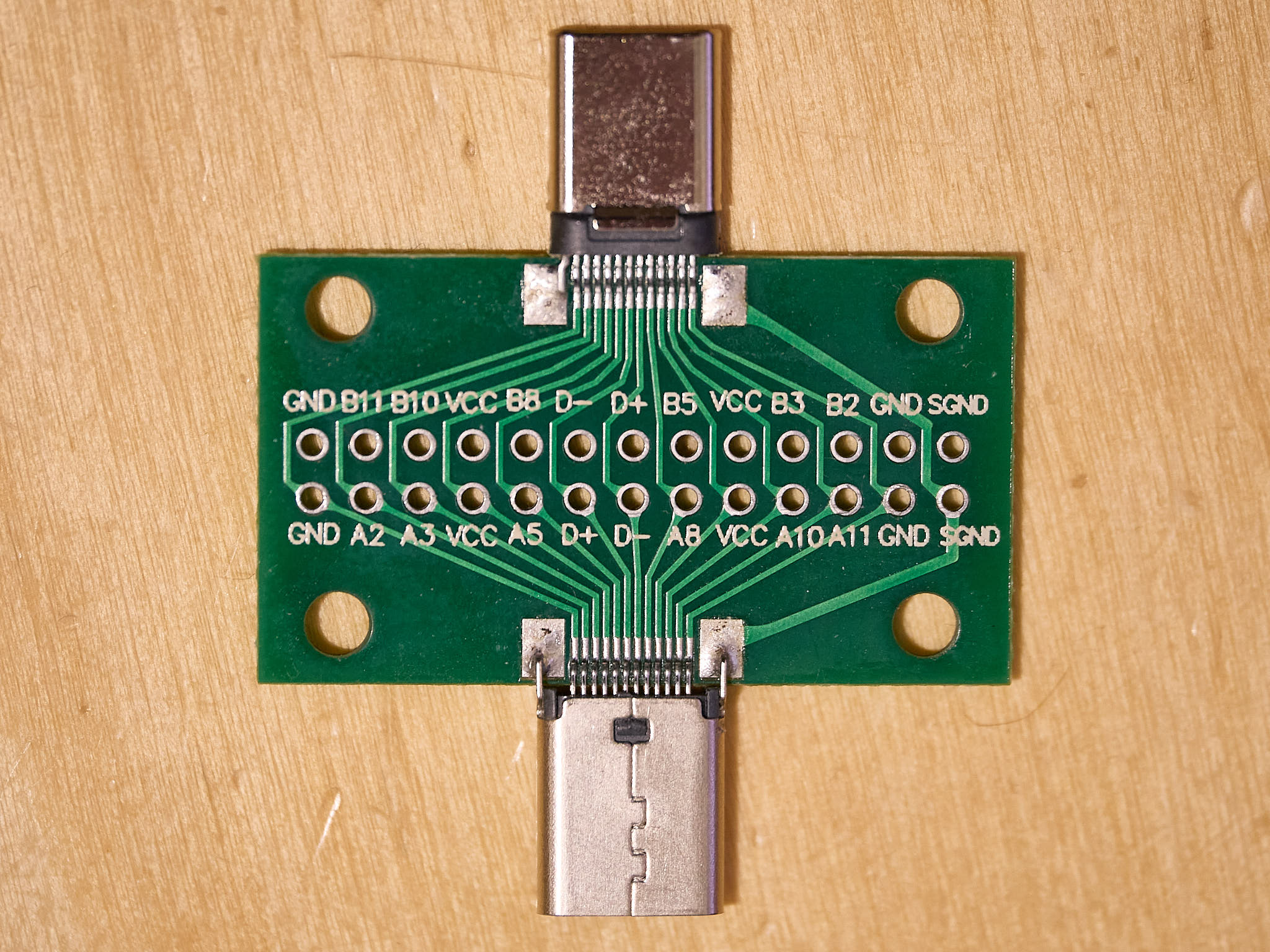
The dimmer output rating is marked as 3 to 5 V at 2.0 A. From the measurements, the actual current flowing to the LEDs is significantly less. Thus, the ring light seems to lack the wiring/chip needed to trigger the output directly from a charger. So, it looks like the wiring of USB-C connector in the ring light could protect the ring from overvoltage from a USB-C charger. Measurements with a US-B C pass-through breakout board (@fig-usb-c-breakout) showed that only VCC and GND are connected, so, the USB-C female connector in the LS720 ring light is for power only, without any trigger.
::: {#fig-eletrical-tools layout-ncol=1}
{#fig-usb-c-breakout}
{#fig-usb-c-breakout}
Some of the tools used. (a) USB-C pass-through break out, used for measurements with a multimeter. The pins in the male and female connector are all wired, and the exposed metal in the holes serve as test points. (b) USB-C tester (Rui Deng TC66) connected between the LS720 dimmer and the LS720 ring light operated at maximum power.
:::
If dimming is needed, a constant current dimmer can be used instead of the PWM one supplied with the ring light. A male USB-B C connector with a pigtail cable for power (2-pin) can be used to feed power into the ring. I tested that this works using a constant current LED driver. **If such a connection is attempted constant current regulation is a must to avoid destruction of the LEDs as the maximum current is reached at approximately 3.1 V.**
Constant current diming with a better designed dimmer would allow to protect the object being photographed from excess light and heat, or to use wider apertures to avoid loss of resolution by diffraction. Even a constant current fixed LED driver could be an improvement as the original driver is prone to switch itself on by itself and the dimming knob can be easily disturbed. At least in principle, the dimmer could be also replaced with a direct connection of the ring light to a 3.3 V regulated power supply. However, the current flowing through LEDs increases as they get warmer, possibly leading to their damage or destruction.
I have expanded this section after after I used an USB-C pass-through break-out board to investigate how the dimmer is connected to the ring light, and I have driven the ring light with a dimmer based on the constant current approach.
:::
## Polarization
Polarization is extremelly effective at removing reflections ([@fig-ls720-polarization]). Even if exposure needs to be increased with the polarizers crossed as directly reflected light is bloked from reaching the camera, it remains strong enough. This makes this and similar ring lights with polarizer a lot more useful than ring light lacking polarisers. This is because light from ring lights impings on the object being photographed from very near the lens making reflected light shine back into the lens front.
in the LED array in [@fig-ls720-polarization] the LED chips are embedded in a clear silicone compound, which contains some bubbles, dust and other imperfections.
::: {#fig-ls720-polarization layout-ncol=2}
{#fig-ls720-arr-parallel}
{#fig-ls720-arr-partial}
{#fig-ls720-arr-crossed}
{#fig-ls720-arr-crossed-2x}
Photographs of a 12 channel LED array, with one type of LED chips per channel. The shinny metal base onto which the LED chips are attached is highly reflective. For these photographs I illuminated the LED array with the LS720 ring light mounted on the lens. I used an OM-1 digital camera with a M.Zuiko 90 mm 1:3.5 Macro lens on a copy stand (as in [#fig-MZ90]). Between a), b) and c) I rotated the polarizer. Auto-exposure settings changed by -3.7 EV by supressing the strong reflections. d) Potograph with the polarizer as in c) but with the lens plus ring light distance to to subject reduced to reach close to 2x magnification on the sensor. The square metal plate onto which the LED chips are attached measures $21 \times 21\,\mathrm{mm}$, while the LED chips are $\approx 1 \times 1\,\mathrm{mm}$. The photographs in a), b) and c) are slightly cropped.
:::
## Example photographs
I took a few test photographs, using the ring light with the dimmer set at full power. In the case of the circuit board, I used in-camera focus stacking ([@fig-ls720-circuit-board]). In the case of the faba bean and cumin seed ([@fig-ls720-faba-bean; @fig-ls720-cumin-seed]), I used focus bracketing in camera and assembled the stack with [Helicon Focus](https://www.heliconsoft.com/). The scale is a single uncropped image obtained using the teleconverter ([@fig-ls720-4x-scale]).
::: {#fig-ls720-examples layout-ncol=2}
{#fig-ls720-circuit-board}
{#fig-ls720-faba-bean}
{#fig-ls720-cumin-seed}
{#fig-ls720-4x-scale}
Photographs of objects illuminated with the LS720 ring light. OM-1 digital camera on copy stand. a), b), and c) M.Zuiko 90 mm 1:3.5 MACRO IS PRO lens; d) same lens plus M.Zuiko MC-20 2x teleconverter, magnification 4 x. d) Raw file at 80 Mpix using sensor shift high resolution mode of a clear and very shiny flexible scale for microscopy.
:::
## Conclusions
The Mechanic LS720 ring light is useful for macrophotography,
* only with macro lenses of relatively long focal lengths,
* after adding a mask to control reflections,
* if imperfect colour reproduction is acceptable or a custom colour profile is used,
* at specific distances where illumination is spatially uniform.
* Dimming with the original dimmer is usable only at slow shutter speeds,
* but a different dimmer based on CC-dimming can be easily adapted.
* Lacking a difuser, if the polariser is not set to maximum effect, reflections of the LEDs can a major problem.
The manufacturer's description is misleading in two respects: 1) the filters do not have an effective anti-reflection coating, and 2) the advertised power rating is at the input to the dimmer, not the electrical power used to drive the LEDs.
In spite of its limitations, I consider the Mechanic LS720 ring light a useful addition to my tool-box for macro photography, and I expect to use it rather frequently. When needed, I will substitute the PWM dimmer supplied, with one based on constant current (CC), as this makes dimming usable at all shutter speeds.