---
title: "UV-A-Induced VIS Fluorescence---Methods"
subtitle: "UV-A sources, filters, cameras and other equipment"
author: "Pedro J. Aphalo"
date: 2022-10-15
date-modified: 2025-11-22
toc: true
categories: [equipment, illumination, filters]
keywords: [LED light, ultraviolet]
bibliography: uvaivf-methods.bib
nocite: |
@*
format:
html:
code-fold: true
code-tools: true
lightbox: auto
image: images/lichens-UVIVF-01.jpg
license: "CC BY-SA"
draft: false
editor:
markdown:
wrap: 72
abstract: |
This page contains notes about photography of ultraviolet-A-radiation induced visible fluorescence. I discuss methods in detail and provide examples of higher plants, lichens and mosses. I describe the ultraviolet-A sources, UV-pass and UV-blocking filters, lenses and cameras that I use, as well as camera settings I use.
---
{{< include /_includes/uva-warning.qmd >}}
::: callout-tip
# Viewing photographs
Clicking on photographs opens a gallery view with them displayed at a
larger size and at higher resolution. This view also allows navigation
among multiple photographs from a given Figure.
:::
{{< include /_includes/folded-code-tip.qmd >}}
```{r, message=FALSE}
library(photobiology)
library(photobiologyFilters)
library(photobiologyLamps)
library(photobiologyLEDs)
library(photobiologyWavebands)
library(photobiologyPlants)
library(ggspectra)
library(patchwork)
library(knitr)

my.fig.heigth <- 4.5
my.fig.width <- 7
knitr::opts_chunk$set(
  fig.width = my.fig.width, fig.height = my.fig.heigth, dev = "svg", out.width = "975%", message=FALSE
)

theme_set(theme_bw(12) + theme(legend.position = "top"))
photon_as_default()
```
## Fluorescence
Fluorescence occurs when a molecule absorbs radiation and re-emits the
absorbed energy also as radiation. The usual case is the capture of a
single photon, dissipation of a (small) fraction of the energy as heat
and the emission of the rest of the energy as a new photon. As the
emitted photon carries less energy than the absorbed one, fluorescence
takes place at a longer wavelength than the absorbed radiation.
Both UV and visible light can induce the fluorescence of chlorophyll in
plants. Strong fluorescence is emitted at wavelengths near 685 nm and
740 nm, by chlorophyll-_a_ and chlorophyll_b_. Phenolic acids fluoresce
in the blue and green regions. Pigments in lichens, some mushrooms and
even insects (as well as scorpions) fluoresce in a variety of bright pure
colours.
We do not see the fluorescence in normal daylight as the high
sensitivity of human vision with a peak in green prevent it. With a
camera modified to increase sensitivity to infra-red radiation and a
filter that blocks wavelengths shorter than 680--700 nm the fluorescence
can be imaged. A flash of strong light is most effective and is used in
the study of plant's photosynthesis ([@fig-faba-chl-fluorescence]).
::: {#fig-faba-chl-fluorescence}
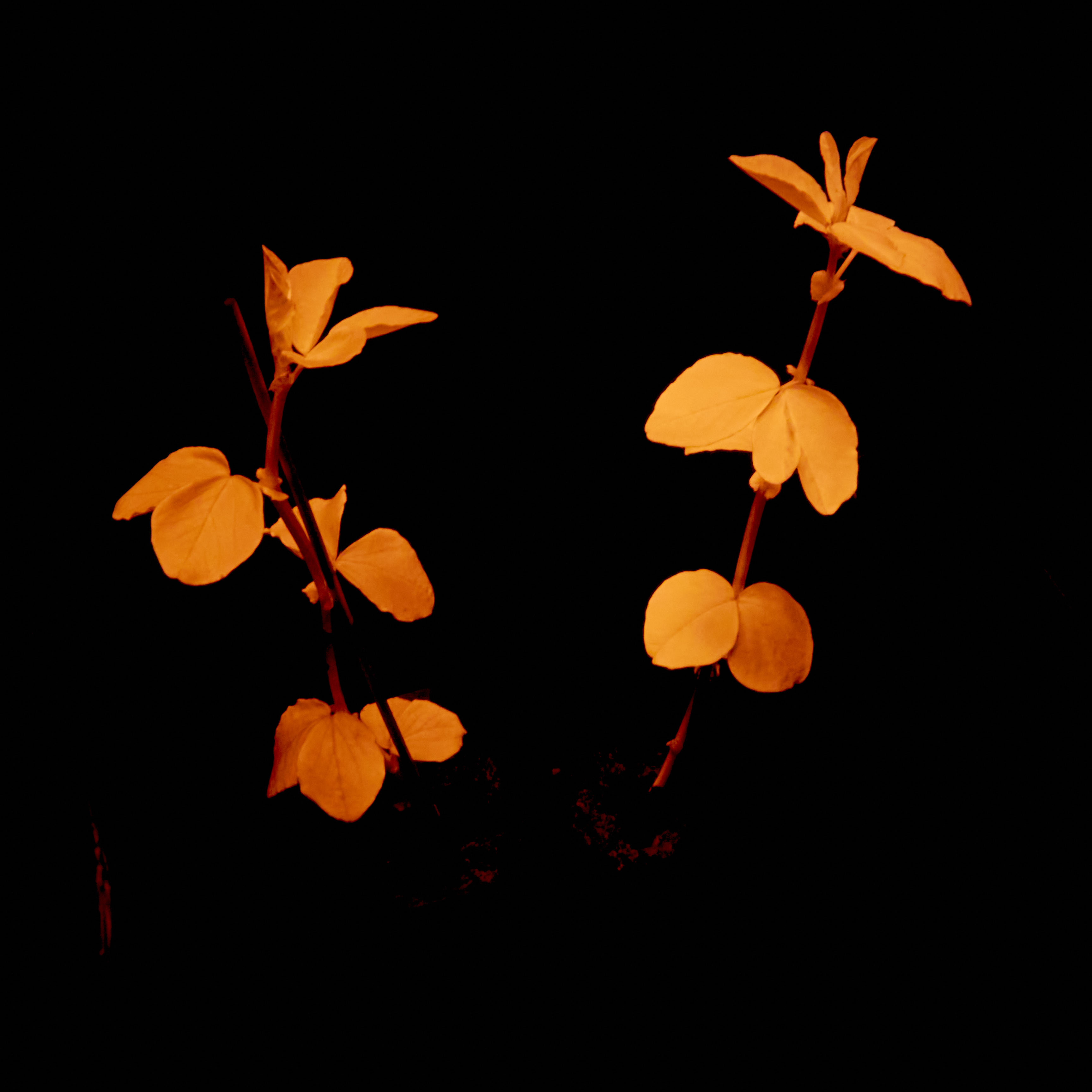{fig-alt="Two young fava bean plants glowing orange-red on a dark background."}
NIR chlorophyll fluorescence induced by a flash of white light in plants
of fava beans. Camera: full-spectrum converted Olympus E-M1, Sigma 30 mm
1:2.8 DC DN MFT lens, Heliopan RG680 filter on lens. Strong white light
illumination from a device used to study photosynthesis of plants.
:::
The fluorescence spectrum can be measured, with some difficulty with
an array spectrometer and a UV-A flashlight resulting in very noisy data.
```{r, warning=FALSE, message=FALSE}
#| label: fig-lettuce-leaf-fluo-spct
#| fig-cap: Whole-leaf fluorescence spectrum from a lettuce leaf illuminated with UV-A1 radiation at 365 nm from a flashlight and measured on the opposite side of the leaf with a Maya 2000 Pro array spectrometer with a cosine diffuser. (Heavily smoothed.)
load("data/UVA365nm_source_003.spct.Rda")
autoplot(clean(smooth_spct(UVA365nm_source_003.spct, method = "supsmu", na.rm = TRUE)),
         geom = "spct",
         span = 55,
         range = c(400, 800),
         label.qty = "contribution.pc")
```
Of course it can be also measured with
more sophisticated equipment to obtain a clean fluorescence spectrum, in this case for a wheat leaf, measured
under 355 nm excitation ([@fig-wheat-leaf-fluo-spct]).
```{r, warning=FALSE, message=FALSE}
#| label: fig-wheat-leaf-fluo-spct
#| fig-cap: Whole-leaf fluorescence spectrum from a wheat leaf illuminated with UV-A1 radiation at 355 nm.
autoplot(leaf_fluorescence.mspct, span = 11, geom = "spct")
```
The quantum yield of fluorescence depends on the molecules involved. In
most cases the fraction of the incident radiation that is emitted as
fluorescence is small, frequently not even detectable. When we
illuminate a plant or object with ultraviolet-A (UV-A) radiation, only
some of its components, if any, fluoresce strongly, emitting visible
light (VIS) and NIR radiation of specific wavelengths.
To induce fluorescence across the whole visible spectrum we have
to use radiation of shorter wavelengths, such as UV-A radiation. Our
eyes' low sensitivity to UV-A radiation and easily available eyeglasses
and goggles that block all UV radiation help in allowing us to see the
fluorescence without it being overwhelmed by the radiation used as
excitation.
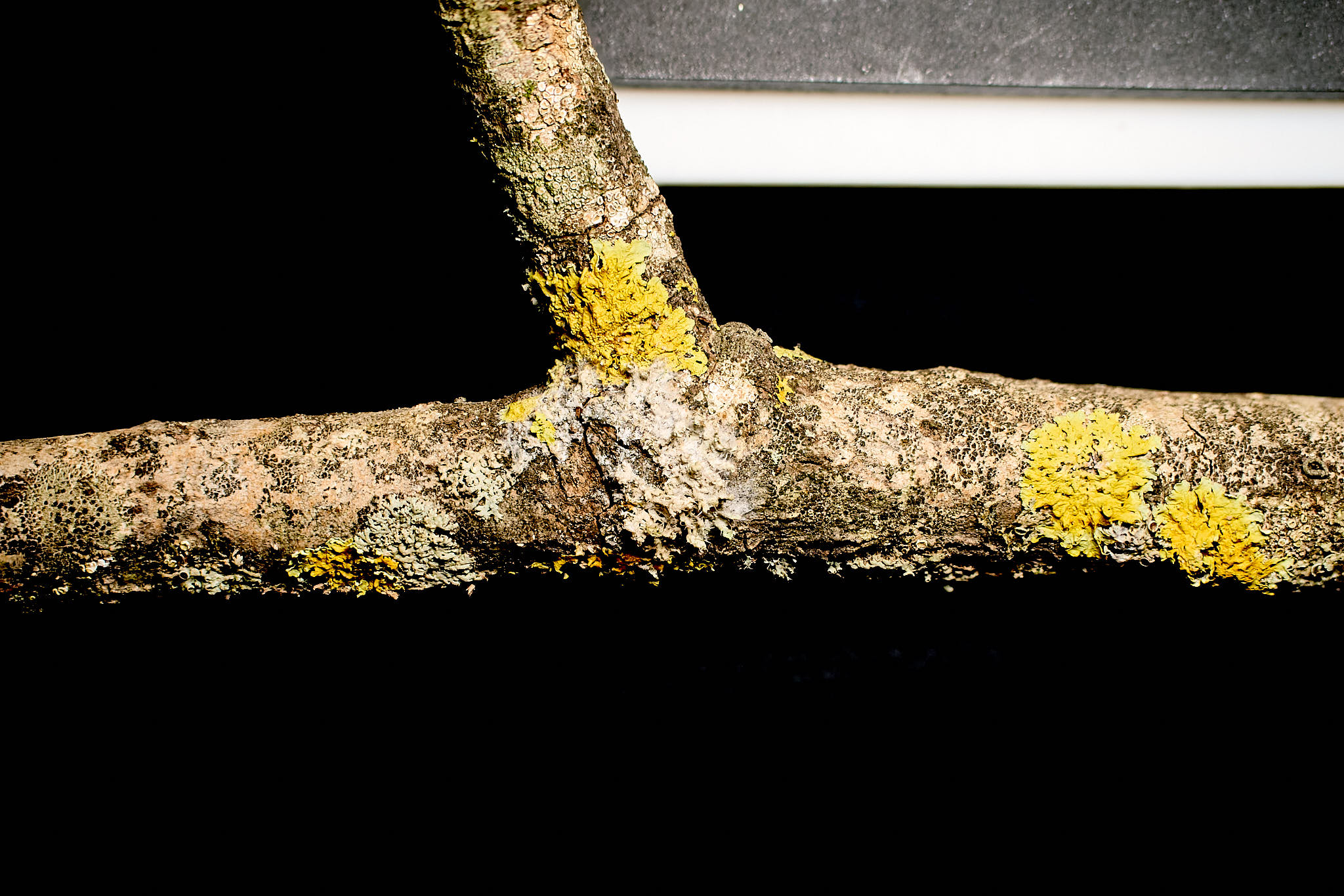
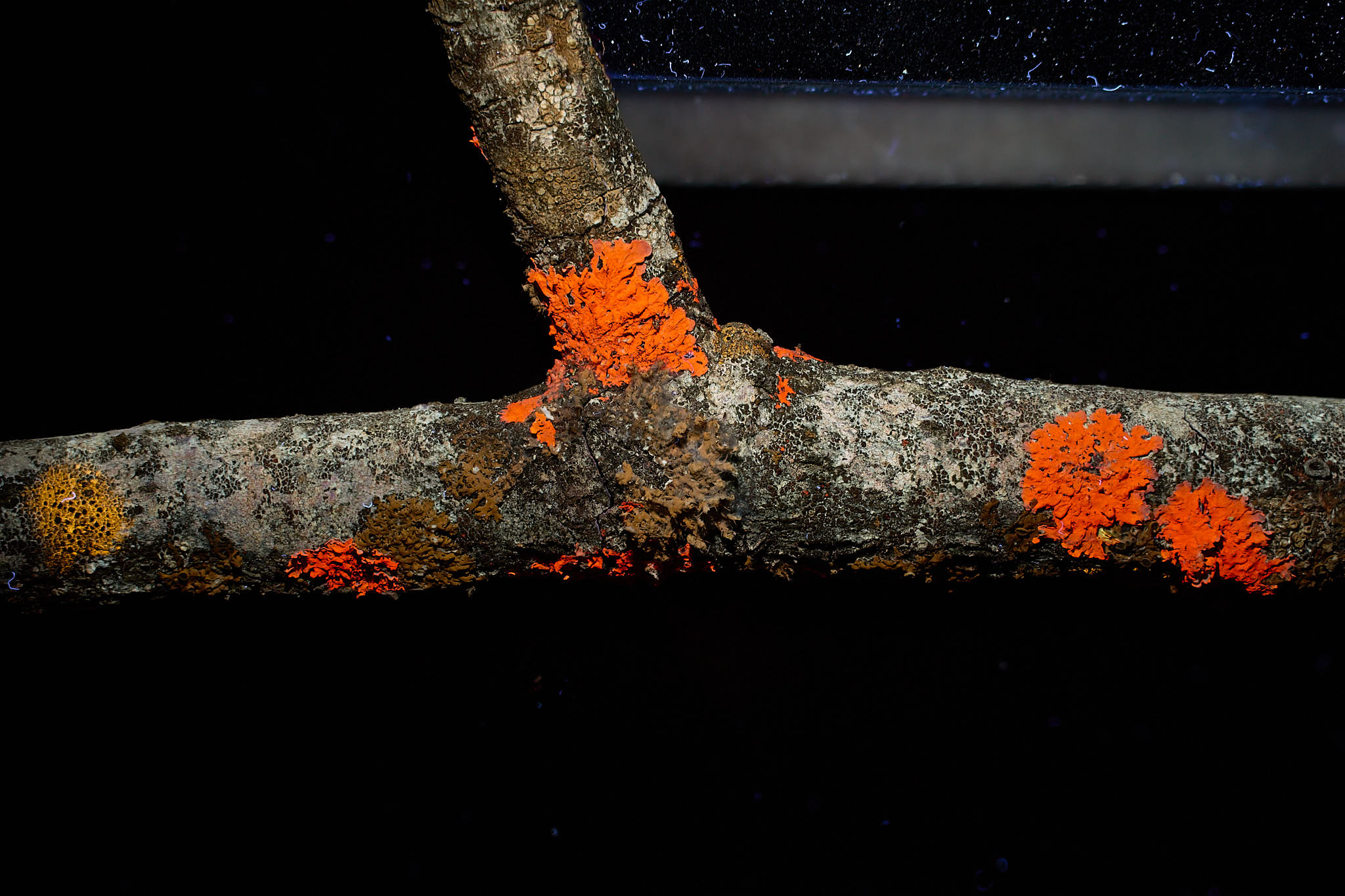
Different lichens contain pigments that fluoresce brightly when exposed
to UV-A radiation ([@fig-lichens-fluo-01]). Colours of the fluorescence
vary between yellow, red, occasionally blue and rarely green.
::: {#fig-lichens-fluo-01 layout-ncol="2"}
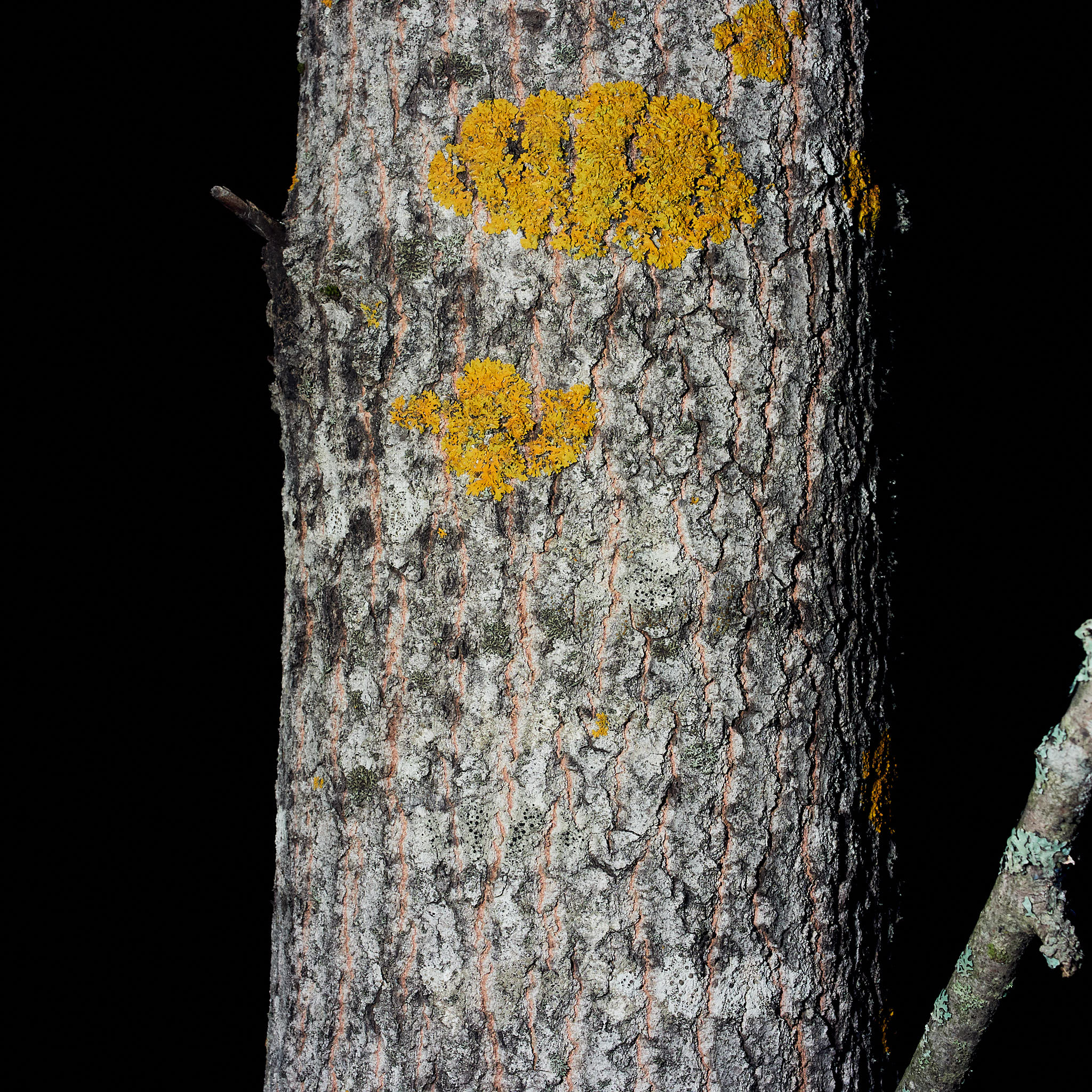{fig-alt="Trunk of an aspen tree in white light with yellow and grey lichens."
group="lichens01"}
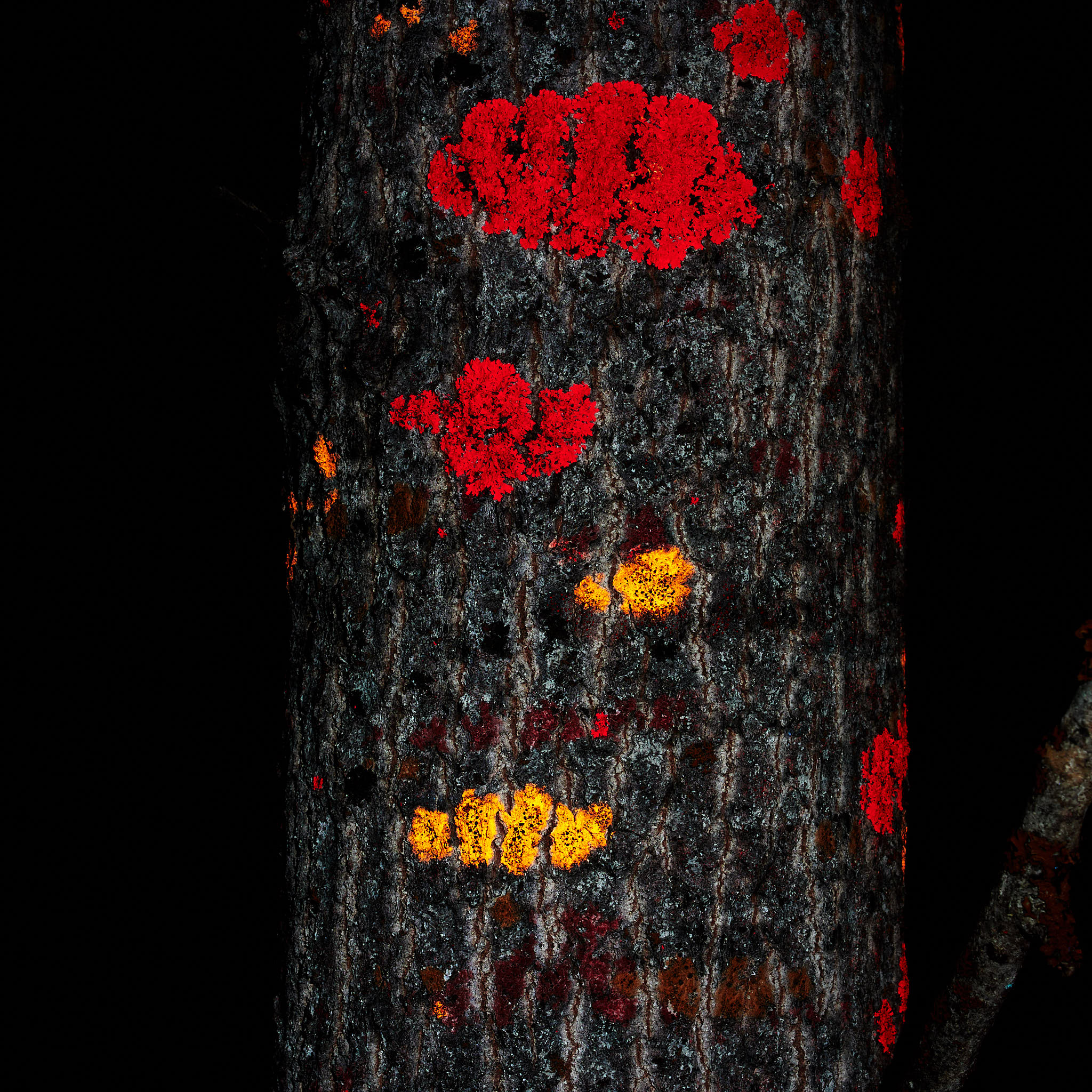{fig-alt="Trunk of an aspen tree in UV-A with the same lichens glowing red and yellow."
group="lichens01"}
Lichens on the trunk of an aspen tree, photographed at night illuminated
with either white light or ultraviolet-A radiation. Camera: Olympus E-M1
Mk II, Sigma 30 mm 1:1.4 DC DN MFT lens. A: White light illumination
from a white LED light source, B: UV-A illumination (365 nm Convoy 2+
flashlight with VIS-blocking filter) and Tiffen Haze 2A + Firecrest
UV400 filters on lens. Photographs white-balanced and edited in Capture
One Pro version 16.5.
:::
::: callout-note
# Can the flourescence be emitted at a shorter wavelength than the excitation?
It can in exceptional cases when the energy acquired by a molecule by
absorbing more than one photon is emitted as a single photon. In such a
case, even if there is thermal energy dissipation, and the emitted photon
carries less energy than the sum of the absorbed photons, it will carry
more energy than each absorbed photon individually. *This happens only
in exceptional cases because the re-emission is normally fast.*
:::
## Photographing fluorescence
I have in Flicker some galleries of fluorescence images.
[Lichens photographed at the Jardin botanique du col du Lautaret, French Alps, 2019](https://flic.kr/s/aHsmDXGTvR)
[Various photographs taken indoors, at home, Helsinki, Finland](https://flic.kr/s/aHsmUGu7MG)
[Various photographs taken outdoors at night, Loppi, Finland, 2019-2020](https://flic.kr/s/aHBqjAuFCM)
In many respects photographing fluorescence is similar to photographing
in low-light. It usually requires long exposure-times and use of a
tripod or other camera support. In addition we need to make sure that
what we photograph is really fluorescence emitted by the object being
photographed rather than contamination by excitation radiation, ambient
light or even fluorescence by nearby objects.
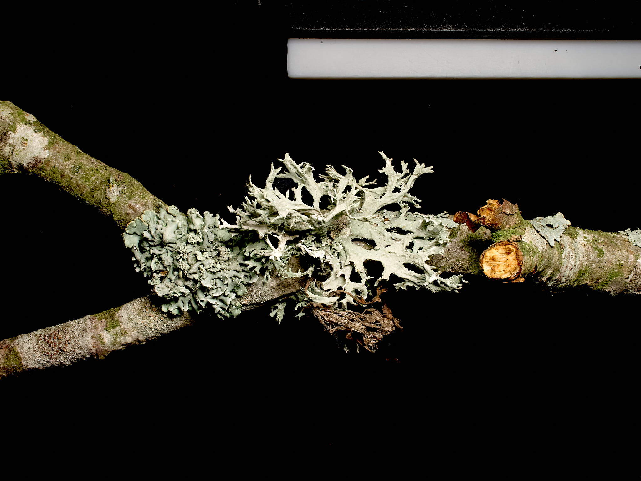
:::: callout-tip
# Is it really fluorescence?
We can check if the light in the image is from the light source or not
by including a "white" reflectance reference (\[#fig-lichens-fluo-02\]).
I use a slab of white PTFE (Teflon) about 5 mm thick. It should have a
matte surface and be clean, as dirt can easily fluoresce. (I use wet/dry
sandpaper 600 grit under running water from time to time to clean it.)
If the white slab appears darker, nearly black, in an otherwise brighter
image, we can conclude that what has been recorded is fluorescence.
::: {#fig-lichens-fluo-02 layout-ncol="2"}
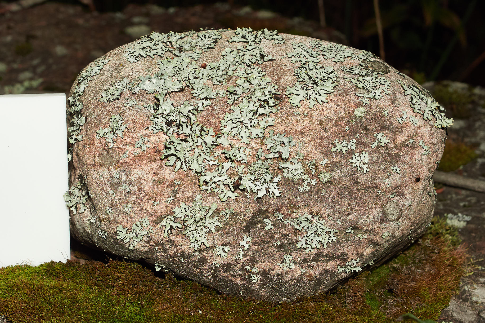{fig-alt="Rock in white light with grey lichens and the reference slab looking white."
group="rock01"}
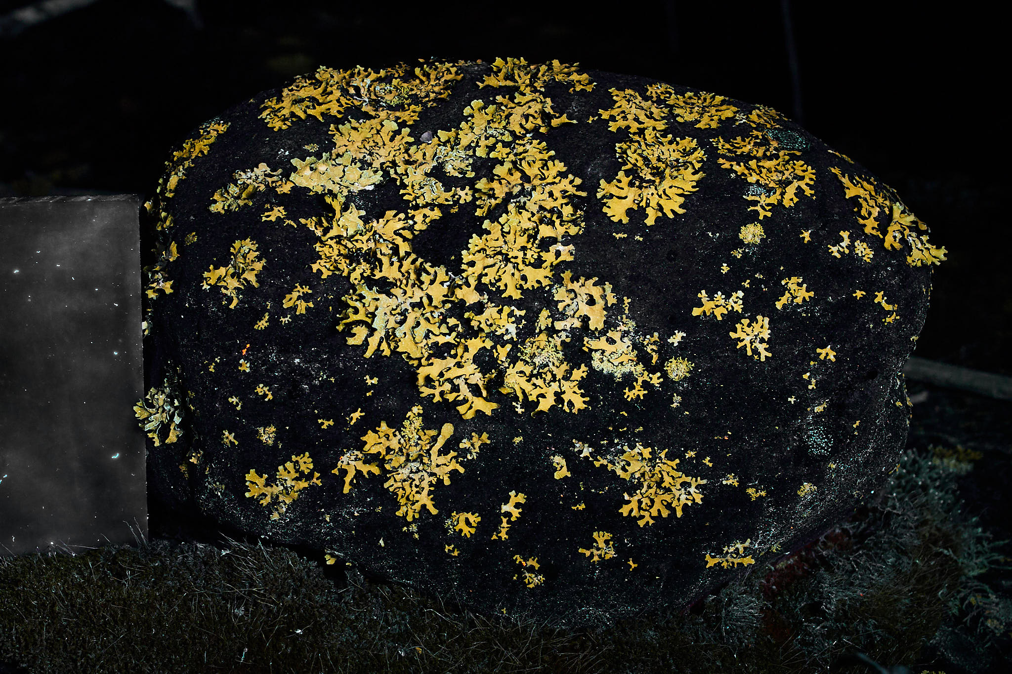{fig-alt="Rock in ultraviolet-A radiation with lichen glowing yellow and the reference slab looking almost black."
group="rock01"}
Lichens on a rock. To the left of the rock the white PTFE slab can be
seen. Camera: Olympus E-M1 Mk II, Sigma 30 mm 1:1.4 DC DN MFT lens. A:
White light illumination from a white LED light source, B: UV-A
illumination (365 nm Convoy 2+ flashlight with VIS-blocking filter) and
Tiffen Haze 2A + Firecrest UV400 filters on lens. In B: a weak
blue-violet shine on the reference slab was subtracted from the whole
image. Photographs white-balanced and edited in Capture One Pro version
16.5.
:::
::::
Some equipment and suitable surroundings are needed when photographing
fluorescence. The items below are discussed in more detail in later
sections.
- Location, outdoors: At night, far from any artificial illumination in a moon-less night.
- Location, indoors: In a dark room, with no strongly fluorescent objects except the one being photographed.
- A source of UV-A radiation: A flash light based on a good UV-A LED is very convenient, especially outdoors. Indoors, mains powered LED or fluorescent "black light" lamps could be also used.
- Exciter filter: A high-quality VIS-blocking filter is needed in the light source.
- Barrier filter: A high-quality UV-blocking filter is needed on the camera lens.
- Camera: A digital mirrorless (ML) system camera is preferable, but in principle any camera whose controls allow long exposures is enough. A converted camera is needed only to photograph NIR fluorescence.
- Objective: Most lenses work, but a lens with an f/2.8 or wider maximum aperture is best.
- Support: Exposure times between 20 s and a few minutes are common, so the camera must be mounted so that it does not move.
- Subject: Easier to photographs are several lichens that fluoresce brightly, tolerate handling and do not wilt quickly. Of course, chlorophyll fluorescence can be strong under some conditions. Blue fluorescence is common in grasses.
### Location and surroundings
As fluorescence is weak compared to other light sources it can only be
observed and photographed in the absence of other sources of visible
light. Outdoors, normally at night and far from street lamps and other
light sources, or in a darkened room indoors. The main problem indoors
is the presence of fluorescent objects other than those of interest.
These include paper, light-coloured and white cloths and clothes, and
even some plastic objects. The
reason why UV-induced blue fluorescence is pervasive indoors is that
blue-fluorescing compounds are normally added to white paper and some
white plastics so that they look whiter and brighter. In fact, these
chemical compounds are frequently called whiteners. Many laundry powders
and liquids contain whitening and/or brightening agents that remain on
clothes after washing them. Less frequently, white and light-coloured
paints can be formulated with fluorescent substances in addition to
white pigments that reflect visible light.
::: callout-note
Post-it and similar yellow notes do not fluoresce much when exposed to
UV-A radiation and can be used for labels or for taking notes.
:::
### UV-A sources
I find UV-A LEDs most useful as UV-A sources as they intrinsically emit
little VIS radiation. Little is anyway in most cases too much when
photographing fluorescence and they need to be combined with optical
filters that effectively block visible radiation. Flash lights and other
small sources of UV-A are readily available as they are used for
checking authenticity of bank notes, cleanliness (urine fluoresces
strongly) and searching for scorpions in houses. LEDs emitting at a
wavelength of 365 nm are the most suitable
([@fig-LedEngin365nm]), as radiation at this wavelength is weakly visible.
LEDs emitting at longer wavelengths are more
difficult to use because we see these wavelengths better, which makes
seen the fluorescence more difficult. A key difficulty is finding a good
enough barrier filter at say 450 nm or 480 nm. Such filters exist, but
being special can be very expensive, but required to block violet and blue
light that such LEDs emit.
LEDs emitting at
wavelengths shorter than 360 nm tend to have much weaker UV emission,
making them cumbersome for regular use. These LEDs are also more expensive
and require more care to ensure safety.
```{r}
#| label: fig-LedEngin365nm
#| fig-cap: Emission spectrum of an UV-A LED with nominal peak of emission at 365 nm. LED type 3W SMD LED type LZ1-10UV00 from LED Engin.
autoplot(leds.mspct$LedEngin_LZ1_10UV00_365nm, geom = "spct")
```
Although the emission of LEDs takes place in a relatively narrow peak, the tails
can extend tens of nanometres on either side of the wavelength
at the maximum emission ([@fig-LedEngin365nm-zoom]). Furthermore, the peak
wavelength can shift by a few nanometres as the LED temperature and/or
current used to drive it changes.
```{r}
#| label: fig-LedEngin365nm-zoom
#| fig-cap: Emission spectrum of a bare UV-A LED with nominal peak of emission at 365 nm. LED type 3W SMD LED type LZ1-10UV00 from LED Engin OSRAM. Close view of wavelength-range surrounding the peak of emission.
autoplot(leds.mspct$LedEngin_LZ1_10UV00_365nm, geom = "spct", range = c(315, 450))
```
A flashlight with a Nichia UV-A1 LED with nominal peak of emission at 365 nm, filtered with a VIS blocking filter has a much shorter right-side tail.
```{r}
#| label: fig-Convoy2p
#| fig-cap: Emission spectrum of a Convoy 2+ flashlight with a 3W Nichia LED emitting at 365 nm and a ZWB2 UV-pass VIS-blocking replacement filter installed..
autoplot(smooth_spct(normalise(lamps.mspct[c("Convoy.S2plus.LED.UVA.flashlight")], norm = "undo"),
                     method = "supsmu", strength = 0.001), geom = "spct",
         range = c(315, 450))
```
Black-light-blue and UV-A fluorescent tubes can also be used indoors, or
where mains power is available. They usually emit over a broader range
of wavelengths than individual UV LEDs, something that can sometimes be
an advantage ([@fig-Qpanel340-lamp]). Many of them emit a significant
fraction of the total radiation in the visible. This makes fluorescent
tubes much less suitable as blocking the unwanted VIS and NIR radiation is
more difficult than with UV-A LEDs.
```{r, warning=FALSE, fig.height=my.fig.heigth * 1.8}
#| label: fig-Qpanel340-lamp
#| fig-cap: Emission spectra of black-light-blue (BLB) fluorescent tube and of a UV-A fluorescent tube.
autoplot(lamps.mspct[c("QPanel.FT.UVB340.40W", "Eiko.F36T8.BLB")],
         geom = "spct", idfactor = "Lamp", facets = 1, span = 101)
```
In principle a photography flash modified to emit UV-A radiation could be used as a
light source. Xenon lamps do emit over a very broad range of
wavelengths, making them very difficult to filter effectively ([@fig-flash-spct]).
```{r}
#| label: fig-flash-spct
#| fig-cap: Emission spectra Xenon flash lamp with a glass envelope and no filter. Godox AD200 flash with a non-standard flash bulb in a bare-lamp head.
autoplot(lamps.mspct$Godox.XeF.AD200.H200.flash, geom = "spct", span = 51)
```
To be able to photograph fluorescence isolated from VIS and NIR radiation,
without contamination from the UV-A sources, it is necessary to use UV-pass
VIS-blocking filters on the light source. This barrier filter should completely
block the excitation light making a high-quality UV-blocking filter necessary.
Most UV-filters sold for photography, even from well-known brands, have a cut-in
at too short wavelengths (330 to 380 nm). However, when using a filtered 365 nm
LED as light source, the filter used on the lens has to block wavelengths up
to just past 400 nm.
The best, but rather expensive, option is a Zeiss UV T*
filter, second best is a significantly cheaper Firecrest UV400 filter (from
Formatt-Hitech, apparently gone bankrupt), and a third option is a Tiffen Haze
2A filter (rather difficult to find outside USA). The first two are interference
filters and reflect UV, rather than absorb it. The Tiffen filter, is of a rather
old type and in the tradition of Kodak Wratten filters, has a thin UV-absorbing
gelatine layer encased between two glass sheets. None of these three filters
fluoresce significantly when exposed to UV radiation. In contrast, as discussed
later in this post, most yellow, orange and red filters are made of ionic glass
and when illuminated with UV radiation fluoresce strongly. Thus, they can be
used only behind a UV-blocking filter. Common NIR pass filters used in
photography are also ionic and do also fluoresce, but less intensively.
```{r}
#| label: fig-uv-filters-compared
#| fig-cap: Comparison of the cut-in region of two common UV-blocking photography filters. The Zeiss UV T* filter has a very sharp change in transmittance and is extremely effective in blocking all radiation shorter than 405 nm. The Hoya UV(0) HMC filter has a much more gradual cut-in and effectively blocks wavelengths shorter than 355 nm.
autoplot(filters.mspct[c("Zeiss_UV_Tstar_2.0mm_52mm",
                          "Hoya_UV0_HMC_2.0mm_52mm")],
         range = c(315, 450)) + theme(legend.position = "top")
```
When combined with the emission spectrum of the Convoy 2+ flashlight, the Zeiss
filter "leaks" only $\approx 0.03\%$ of the UV from the flash light, while the
Hoya filters "leaks" $\approx 6.5\%$ ([@fig-uv-filters-compared-with-convoy]).
This leak is more than enough to interfere with the detection of fluorescence.
How much of this radiation reaches the camera sensor depends on the lens, but in
any case it would be a major problem.
```{r}
#| label: fig-uv-filters-compared-with-convoy
#| fig-cap: Comparison of the cut-in UV-blocking by two different photography filters. The Zeiss UV T* filter has a very sharp change in transmittance and is extremely effective in blocking all radiation from the Convoy 2+ UVA flashlight. The Hoya UV(0) HMC filter has a much more gradual cut-in and allows through a significant part of the UVA emitted by the flashlight.
(autoplot(smooth_spct(normalise(lamps.mspct[["Convoy.S2plus.LED.UVA.flashlight"]], norm = "undo") *
                       filters.mspct[["Zeiss_UV_Tstar_2.0mm_52mm"]], method = "supsmu", strength = 0.5),
         range = c(315, 450), ylim = c(NA, 6.2),
         annotations = c("-", "peaks")) + ggtitle("Zeiss UV T* filter") +
   theme(legend.position = "top")) |
(autoplot(smooth_spct(normalise(lamps.mspct[["Convoy.S2plus.LED.UVA.flashlight"]], norm = "undo") *
                       filters.mspct[["Hoya_UV0_HMC_2.0mm_52mm"]], method = "supsmu", strength = 0.5),
         range = c(315, 450), ylim = c(NA, 6.2),
         annotations = c("-", "peaks")) + ggtitle("Hoya UV(0) filter") +
   theme(legend.position = "top")) + plot_layout(axis_titles = "collect")
```
UV-A flashlights are convenient excitation sources for use in
the field ([@fig-convoy-spct; @fig-jaxman-spct]). When the
working distance is relatively short or even illumination is desired, a flood
flashlight works better. In the case of long exposure times and use of "light
painting" the more concentrated beam from the Convoy 2+ allows better targeting
of the UV radiation. The Convoy 2+ is also suitable for illuminating small
objects. Both flashlights have Nichia LEDs with a nominal peak of emission at
365 nm. The exact types were not specified when I bought the flashlights, but
at least the Jaxman Uc1 most likely has a NVSU233B(T) LED from Nichia.
::: {#fig-flashlight layout-ncol="2"}
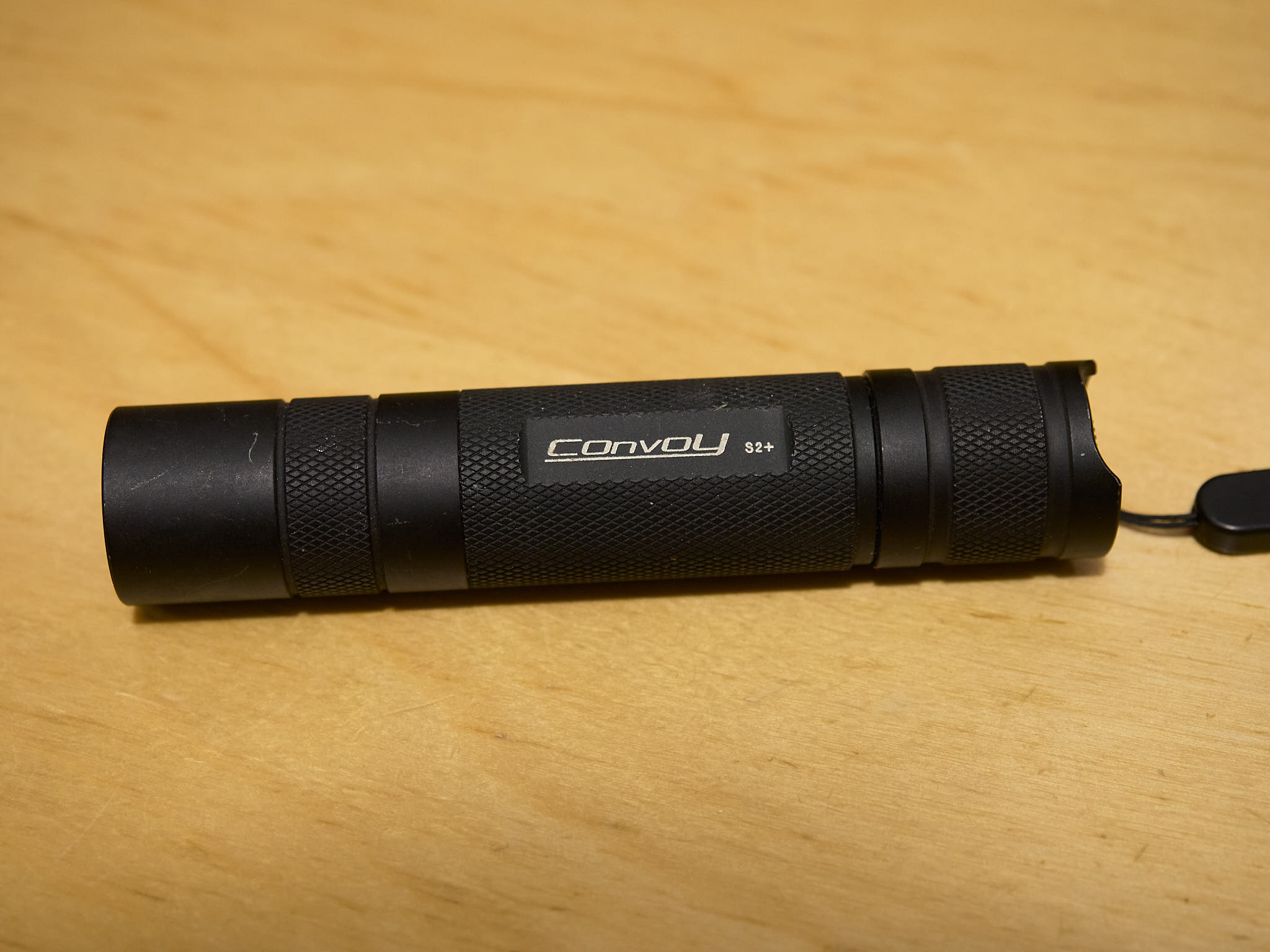{fig-alt="View of a small black anodized aluminium flashlight."
group="flashlights"}
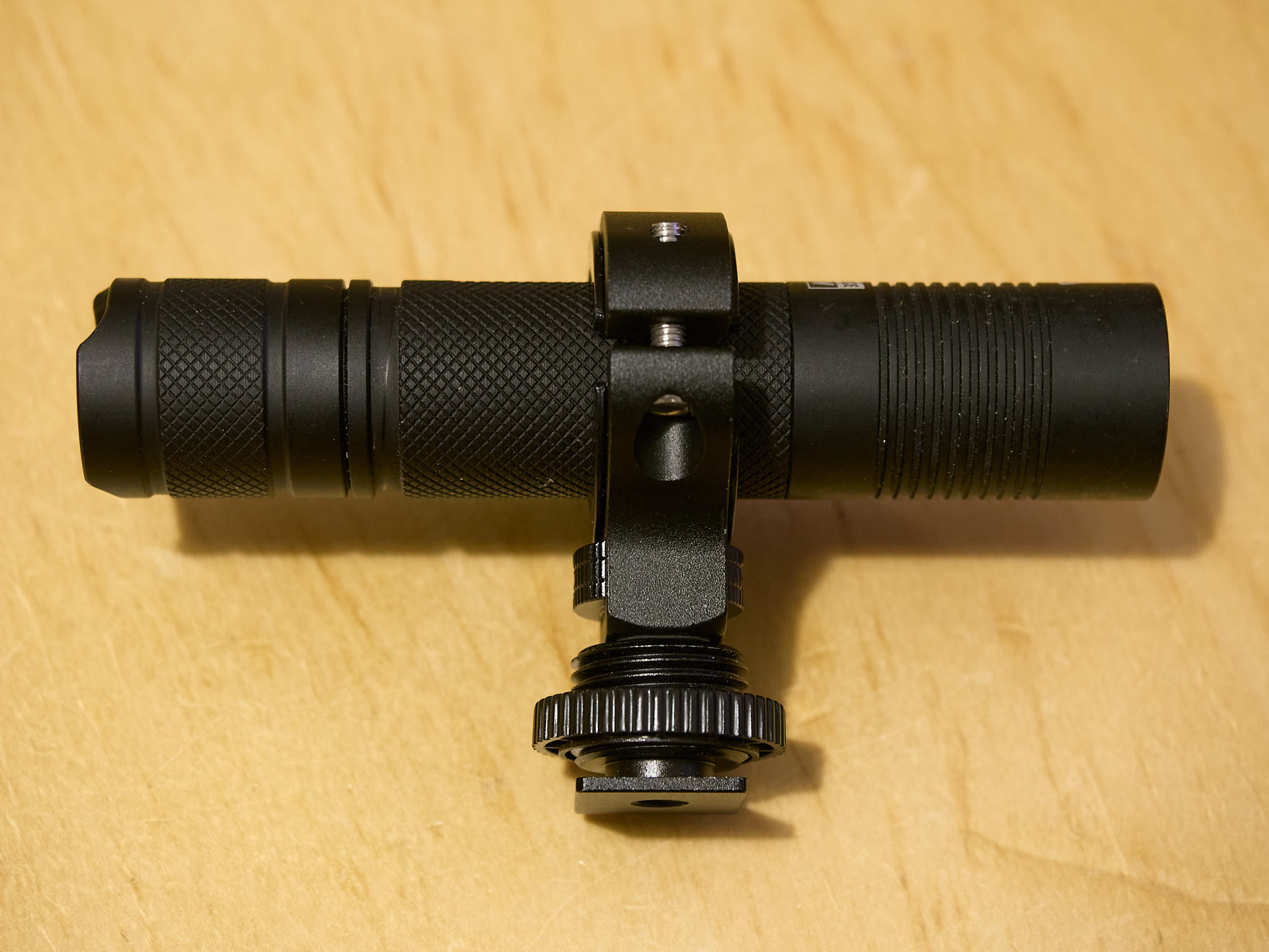{fig-alt="View of a small black anodized aluminium flashlight with a support attached."
group="flashlights"}
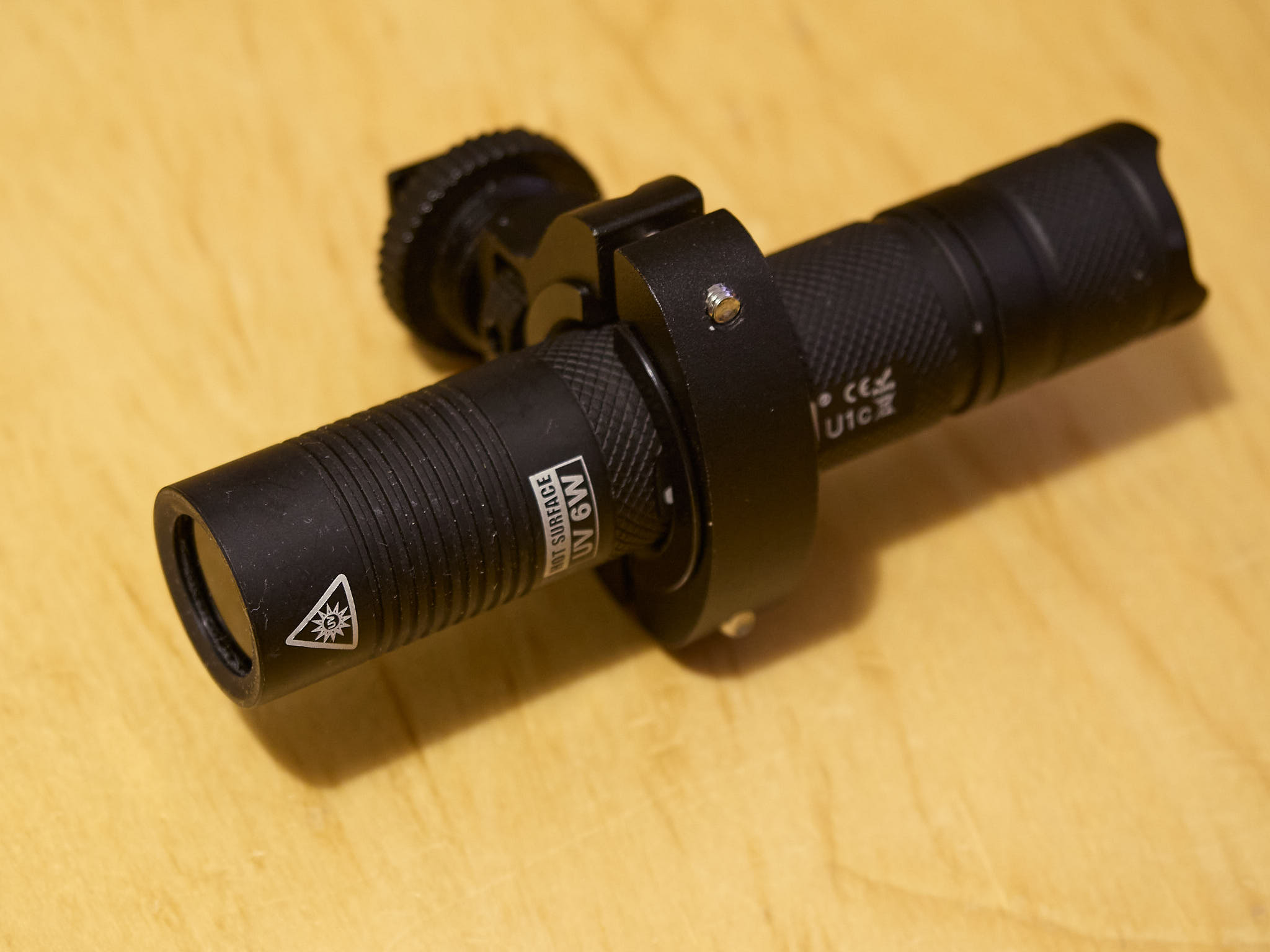{fig-alt="View of a small black anodized aluminium flashlight with a support attached."
group="flashlights"}
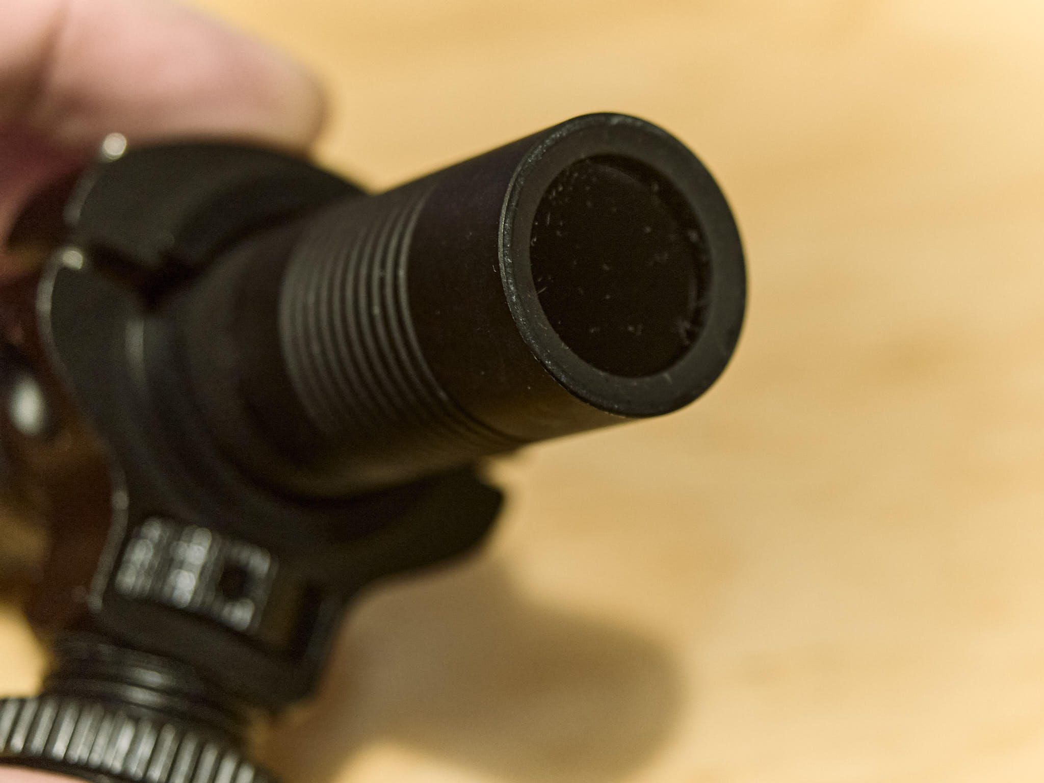{fig-alt="Detail view of the front end of a small black anodized aluminium flashlight showing the black-looking UV-pass and VIS-blocking filter."
group="flashlights"}
Photographs of two very similarly looking UV-A flashlights, that differ
mainly on the LED power and optics. The Jaxman is a "flood" light with a
broad and even beam and the Convoy is a "spot" light with a narrower
beam that is less even. Both flashlights were bought from AliExpress
sellers. The Jaxman was delivered with the VIS-blocking filter
installed, and the Convoy was delivered with a clear glass that I
replaced with a filter bought separately, also from an AliExpress
seller.
:::
The emission spectrum of Convoy 2+ flashlight ([@fig-convoy-spct) and of the
Jaxman Uc1 flashlight ([@fig-jaxman-spct]) have no stray light at longer
wavelengths. Both flashlights use a single Lithium battery of type 16850, that
needs to be removed for recharging.
```{r}
#| label: fig-convoy-spct
#| fig-cap: Convoy 2+ flashlight with a 3W Nichia LED emitting at 365 nm and a ZWB2 UV-pass VIS-blocking replacement filter installed. This flashlight emits a narrow beam of high intensity light with a very obvious hot-spot at the centre.
autoplot(lamps.mspct$Convoy.S2plus.LED.UVA.flashlight, geom = "spct")
```
```{r}
#| label: fig-jaxman-spct
#| fig-cap: Jaxman U1c flashlight with a 6W LED emitting at 365 nm with a built-in filter of unknown brand and type. This is a "flood" flashlight with broader and more evenly illuminated beam.
autoplot(lamps.mspct$Jaxman.U1c.LED.UVA.flood.flashlight, geom = "spct")
```
::: callout-attention
# Choosing an UV-A flashlight
There are many different UV-A or black-light flashlights available. Most
suitable are those emitting at 365 nm, because those emitting at 385 nm
and longer wavelengths emit much more visible light
([@fig-generic-uva-flashlight-spct]), that will either
interfere with the recording of the visible fluorescence or be blocked
by the necessary UV+blue-blocking filter. The flashlight in this example
emitted much less radiation and at longer wavelength.
It is also important to consider
the beam uniformity and breadth. Finally, the power of most flashlights is not
given by sellers as energy flux of UV-A radiation but instead as
electrical power consumed. *In some cases the power values given are
clearly inflated, possibly based on the maximum power the LEDs withstand
rather than the power at which they work in the flashlight or are simply
imaginary, i.e., a hand-held flash light with a rating of 200 W if true
would burn the user's hand in no time!*
```{r}
#| label: fig-generic-uva-flashlight-spct
#| fig-cap: Emission spectrum of a UV-A flashlight that was found very unsuitable in comparison to the Convoy 2+ with Nichia LED.
autoplot(lamps.mspct$Generic.LED.UVA.flashlight, geom = "spct")
```
:::
::: callout-tip
# Convoy 2 and 2+ flashlights
The Convoy 2 and 2+ flashlight have been available from some years. They are
modular, available in many different configurations and even as parts for
self assembly. Flashlights using the same metal body and other parts are sold
under other brands. For example, the Jaxman is very similar to my Convoy 2+
but it has, apparently, a different LED and or optics, and a different LED
driver.
The same body Convoy 2+ is sold with different LEDs installed, different
wavelengths, different powers, and with different packages. There are two
types of reflectors, clear glass, AR-coated glass, and UV-pass VIS-block
windows. Drivers differ in the maximum current, that needs to be matched to
the LED used, and in the user interface. The user interface can allow
dimming or not, and even in some cases have a blinking option. Some drivers
have a single user interface and others have multiple ones to choose from.
One has to be careful with the driver and LED, as a driver that feeds a very
high current to the LED will heat the flashlight. Several of the drivers have
over-heating protection that decreases the power as needed to avoid overheating.
This works when use is briefly, but for a longer photography session one want
constant illumination.
All in all it is best to buy a ready assembled Convoy flashlight with Nichia UV
LED with peak at 365 nm and an UV-pass filter. It is possible, however, to buy
the parts separately, even from different suppliers and assemble a custom
version with a specific LED of one's choice. When I bought the Convoy 2+ it
was not available with a pre-installed filter. Nowadays there are multiple
UV-A versions, and those using LEDs from other brands than Nichia are cheaper.
Configurations ready available are with white light of different colour
temperatures and powers, UV-C. UV-A, blue, green, read and infra-red. Convoy
has an official store in AliExpress ("Convoy Flashlight Store") that has this
and several other flashlights.
The standard configuration uses a 18650 rechargeable Lithium battery.
The body of the flashlight has a diameter of about 20 mm and is 80 mm long.
To hold it I am using a holder that is sold to attach small cameras to the
handlebar of a bicycle. It can be found in AliExpress under the name of
"1/4 Screw Metal Cycling Bike Mount Motorcycle Handlebar Holder for GoPro 13
12 11 10 9 8 Insta360 X3 X4 DJI Osmo Action 4 5 Pro" by multiple sellers. This
adds as attachment point a 1/4"-20 male thread, the standard size used for
cameras. In the photograph, I have attached a male "flash cold shoe".
:::
::: callout-tip
# Flashlight with zoom optics
In the second half of 2025 a UV-A1 flashlight model with zoom optics has become
available both through AliExpress sellers, very cheaply at $\approx 8$ €, and
through a supplier of equipment for UV and IR photography in the USA at a higher
price of $\approx 20$ €. A zoom optics has a rather thick lens instead of a thin
glass window or filter. To be useful in UV-A1 a lens needs to transmit
wavelengths down to 340 nm well. I haven't found any spectra or specifications
for the LED or its power. The cheap and expensive flashlights look identical in
the seller's photographs. Flashlights with zoom optics have earlier been
available for visible light and NIR radiation. I have one of each, and specially
the white light one from LedLenser is excellent and very convenient to use.
The brand of the cheap ones is AloneFire, and reviews of another flashlight of
this brand are negative, indicating badly designed electronics and cooling. The
higher priced version from [Kolari
Vision](https://kolarivision.com/product/kolari-ultraviolet-flashlight-uv/)
could potentially have different electronics in the same body. By comparison,
the Convoy 2+ with 3W Nichia LED costs $\approx 35-45$ € in AliExpress and the
Jaxman Uc1 with 6W Nichia LED and flood optics $\approx 70-75$ € in AliExpress.
:::
### Exciter filter
As mentioned above, if we want to photograph fluorescence across the
whole visible range, the light source used for excitation should not
emit any radiation in the visible range. In fact, more generally we need
to use complementary filters in the light source and camera. Most
frequently we aim at a cross-over of the transmittances so that neither
of the two filters transmits at 400 nm. In practice, we need a
"dead-zone" as the cut-off and cut-in wavelengths of filters have
tolerances of a few nanometres and there can be a gradual change in
transmittance within a range of wavelengths. We look first at the
filters commonly used on light sources or "exciter filters".
Digital cameras have built-in filters on their sensors, but these
filters frequently let through some UV-A radiation. Additional filters must be
chosen considering the light source in use. For example, many UV-pass
filters are not effective at blocking the near infra-red radiation (NIR)
that some cameras can "see" ([@fig-filters-UV-pass]). Fluorescent lamps
emit some NIR radiation while UV-A LEDs do not emit it
(cf. [@fig-Qpanel340-lamp; @fig-LedEngin365nm]).
```{r}
#| label: fig-filters-UV-pass
#| fig-cap: Spectral transmittance of two band-pass UV filters with a thickness of approximately 2 mm. Both of these glass filters are not anti-reflection coated.
autoplot(filters.mspct[c("Tangsinuo_ZWB1_2.1mm_52mm", "Tangsinuo_ZWB2_2.0mm_52mm")],
          geom = "spct", idfactor = "Filter", span = 51)
```
Filter types ZWB1 and ZWB2 from various Chinese suppliers are cheaper
than the German made Schott UG1 and UG5. Specifications are less tight
for the Chinese filters, and can sometimes present optical defects. ZWB1
and ZWB2 are good filter types for use with UV-A LEDs. ZWB1 with a cut-off at a
slightly shorter wavelength can be preferable. A filter thickness of 2 mm or
more is necessary. These filters are usually fine
if bought from reliable suppliers. Filters ready cut to size for common
flashlight types are readily available through AliExpress and eBay
sellers. In LED UV-A light sources it is best to use a VIS-blocking filter.
::: callout-tip
# Visible light as excitation
If we are interested in red or NIR fluorescence we can use blue- or UV +
blue radiation for excitation, with suitable filters and LEDs or lamps.
The Convoy 2+ flashlight is available in innumerable variations, with
different LEDs, different LED drivers, and different reflectors. Even the
parts can be bought as a key, and as it uses a standard sized metal core
printed circuit board for a 3W LED, it would be possible to assemble one
with almost any SMD 3W LED, or even 6W LED. However, instead of assembling
one from parts, I bought a ready-made one with a high power blue LED.
```{r}
#| label: fig-convoy-blue-spct
#| fig-cap: Convoy 2+ flashlight with a 3W-rated OSRAM KB CSLNM1.14 LED emitting at 450 nm and a clear AR coated window installed. This flashlight emits a narrow beam of very high intensity light with a very obvious hot-spot at the centre.
autoplot(lamps.mspct$Convoy.S2plus.LED.blue.flashlight, geom = "spct")
```
As with ionic absorptive UV short-pass filters, blue short-pass filters block NIR
very poorly ([@fig-blue-filters]). So, once again, easiest is to use LEDs as blue-light excitation sources.
```{r}
#| label: fig-blue-filters
#| fig-cap: Transmittance spectra of two types of blue ionic glass filters.
autoplot(filters.mspct[c("Tangsinuo_ZB1_2.0mm_52mm",
                         "Tangsinuo_ZB2_2.0mm_52mm")],
         geom = "spct", idfactor = "Filter",
         annotations = c("+", "wls"),
         span = 101)
```
Differences in blocking efficiency among reflective dichroic filters can be huge ([@fig-blue-dichroic-filters]). The differences in price are also huge, in the case of these
two filters, 20 € compared to 190 € for filters 25 mm in diameter.
```{r}
#| label: fig-blue-dichroic-filters
#| fig-cap: Transmittance spectra of two types of blue dichroic glass filters. A relatively low cost one from UQG Optics and a top-of-the line filter from Thorlabs.
autoplot(filters.mspct[c("Thorlabs_FBH450_40", "UQG_Blue_dichroic_CDB")],
         geom = "spct", idfactor = "Filter", range = c(300, 1050),
         annotations = c("+", "wls"),
         span = 101)
```
:::
## Barrier filter
Barrier filters are used in front or behind the camera lens to block the
excitation light completely. In this case there is an additional
difficulty, yellow, orange and red glass filters themselves fluoresce
when exposed to UV radiation. The solution is to use a UV-blocking
filter that either reflects UV-radiation in front
of the glass filters ([@fig-uvblocker-spct]). These UV-blocking filters can be, as discussed above,
dichroic interference filters or filters
based on a different pigment than the metal ions used in solid glass filters.
Kodak publications from the
film era recommend using a Kodak Wratten 2A or 2B filter in front of
other barrier filters. Tiffen still sells filters very similar to the
Kodak ones. In these filter a coloured light-absorbing film, in most cases using
gelatine as medium for the pigment, is encased between two layers of
clear optical glass. These filters used to be also available as bare
gelatine films. The Zeiss UV T\* filter is based on
interference and reflects radiation below 405 nm, it is AR coated
and less affected by reflections at the transmitted wavelengths than the
Tiffen. The Zeiss T\* filter prevents the fluorescence of other
glass filters as effectively or better than the Tiffen Haze 2A, but it is
rather expensive. The Firecrest UV400 multi-coated filter is nearly as good
as the Zeiss, but significantly cheaper. In actual use, these three
filters work well.
```{r}
#| label: fig-uvblocker-spct
#| fig-cap: Two UV-blocking filters that do not fluoresce when exposed to UV-radiation. A Tiffen Haze 2A, equivalent to Kodak Wratten 2A and Zeiss UV T-* filter. Only the Zeiss filter has an anti-reflection coating.
autoplot(filters.mspct[c("Tiffen_Haze_2A_2.6mm_52mm",
                         "Zeiss_UV_Tstar_2.0mm_52mm")],
         geom = "spct", idfactor = "Filter",
         annotations = list(c("-", "peaks"), c("+", "wls")))
```
In some cases we may want to photograph fluorescence only of some colours. High
quality, dichroic band-pass filters would be perfect for this, but at reasonably
large diameters, are very expensive. These filters are the ones used to separate
fluorescence from different dyes in microscopy. If the aim is to detect all
florescence at wavelength longer than a target, it is possible to use a long-pass
filter. If this is a ionic glass filter, mounted behind a UV-blocking filter
([@fig-filters-VIS-pass]).
```{r}
#| label: fig-filters-VIS-pass
#| fig-cap: Spectral transmittance of some long-pass VIS absorptive ionic glass filters. All these filters have anti-reflection multi-coating.
autoplot(filters.mspct[c("Hoya_Y_(K2)_HMC_2.3mm_52mm",
                         "Heliopan_Yellow_5_SH_PMC_2.3mm_52mm",
                         "Heliopan_Orange_22_SH_PMC_2.2mm_52mm",
                         "Heliopan_Red_25_SH_PMC_2.2mm_30.5mm",
                         "Heliopan_RG665_2.3mm_46mm")],
         geom = "line", idfactor = "Filter",
         annotations = list(c("-", "peaks"), c("+", "wls")))
```
With a camera modified to "see" a broader spectrum by replacement of the
sensor filter, it is possible to photograph NIR fluorescence by blocking
visible fluorescence with long-pass barrier filters
([@fig-filters-NIR-pass]). Compared to an unmodified camera leaks of NIR
from the excitation radiation source become an even bigger problem. Also
NIR long-pass filters require "protection" from UV to prevent their
fluorescence.
::: callout-note
# Fluorescence of glass filters
Yellow, orange, red and NIR long-pass glass filters fluoresce when
exposed to UV-A radiation, most strongly the yellow filters ([@fig-filters-fluorescence]). Yellow
filters do emit a very strong yellow fluorescence. The fluorescence of
orange and specially red filters is not so intense. The
fluorescence of NIR filters is mainly NIR and not visible to a normal
camera or the naked eye. Using a full-spectrum converted camera and a
long-pass filter on the lens, we can see that all four glass filters
fluoresce in the IR.
::: {#fig-filters-fluorescence layout-ncol="2"}
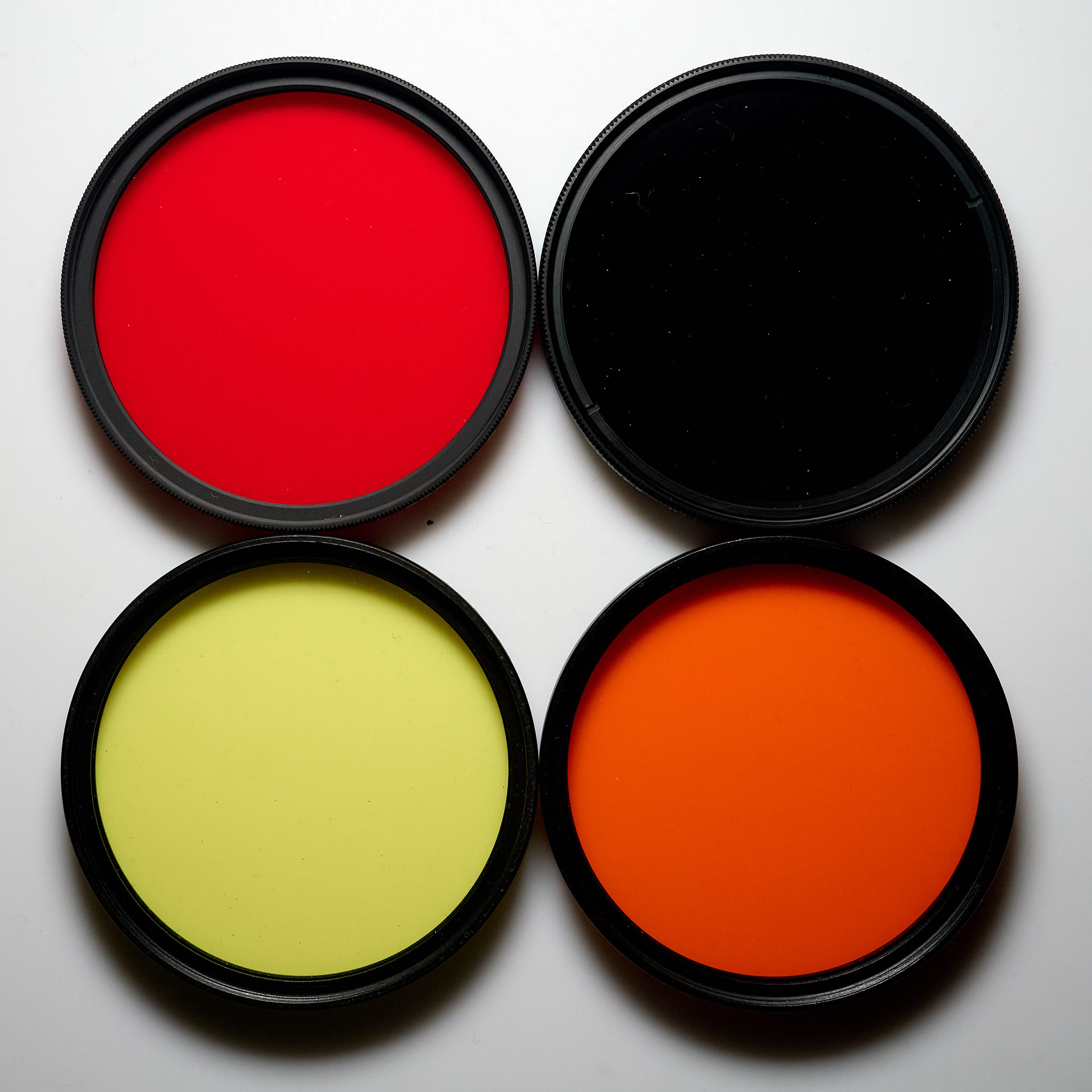{fig-alt="Four long-pass glass filters, yellow, orange, red and NIR"
group="filters"}
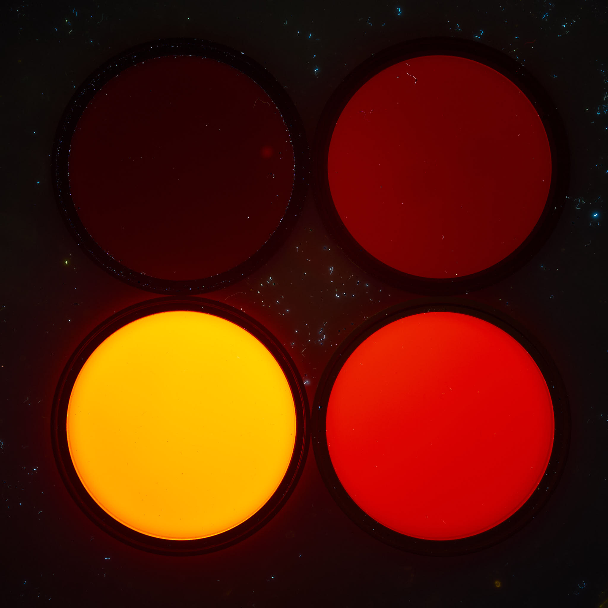{fig-alt="Four filters glowing to varying extents."
group="filters"}
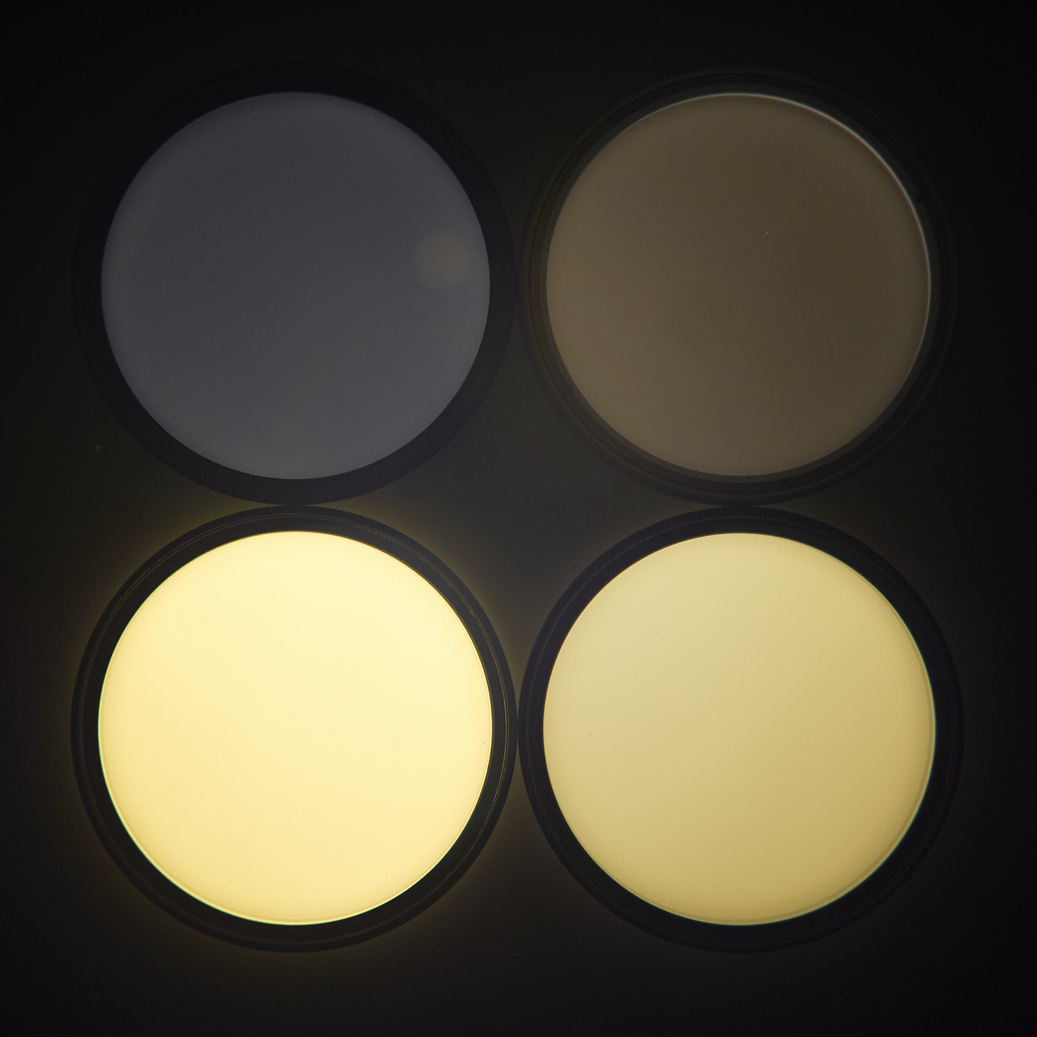{fig-alt="Four filters glowing to varying extents."
group="filters"}
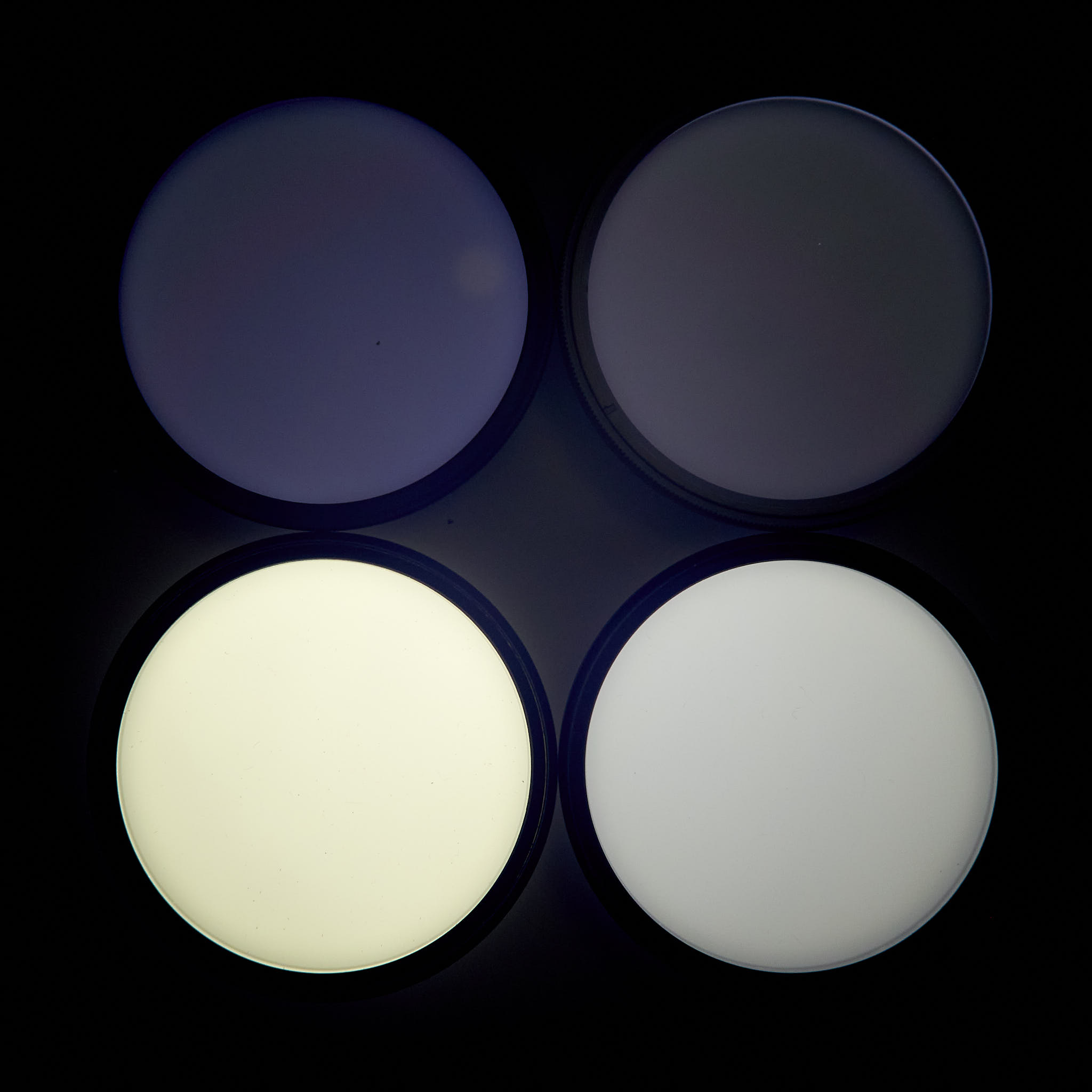{fig-alt="Four filters glowing to varying extents."
group="filters"}
Photographs of four long-pass glass filters under white visible and
ultraviolet-A radiation. The background is in all photographs the same
slab of white PTFE (Teflon), but in B--D the filters used on the camera
lens blocked the UV-A radiation used to excite fluorescence. Clockwise
from the top left corner: Hoya Red 25A (603 nm), Hoya R72 (716
nm),Heliopan Orange 22 (568 nm) and Heliopan Yellow 5 (466 nm), all AR
coated. Light sources: Sunwayfoto FL96 at 5500K LED fill light and
Jaxman Uc1 flashlight. Cameras A, B: Olympus OM-1; C, D: Olympus E-M1
full-spectrum converted. For visible fluorescence barrier filter:
Firecrest UV400 + Tiffen 2A, and for NIR fluorescence Firecrest UV400 +
C:Zomei IR680 or D:Haida IR720 (726 nm) + Tiffen 2A. Lens: M.Zuiko 25
mm 1:1.2 Pro. Photographs white-balanced and edited in Capture One Pro
version 16.5.
:::
The spectra of the fluorescence emission have one or two peaks depending on the filter, and these peaks are at longer wavelengths than those of the radiation used for excitation ([@fig-filters-fluor-spectra]).
```{r}
#| label: fig-filters-fluor-spectra
#| fig-cap: Fluorescence spectra for selected photography filters under excitation from 900 umol m-2 s-1 UV-A1 radiation with peak at 366 nm. A Convoy S2+ flashlight with 3W Nichia LED and a VIS-blocking filter was used as light source (spectrum in [@fig-convoy-spct]). The text header of each panel indicates supplier, filter type and filter thickness.
#| fig-asp: 1.5
names(filters_UVIVIF.mspct) <- gsub("_|52mm$", " ", names(filters_UVIVIF.mspct))
autoplot(filters_UVIVIF.mspct,
         facets = 2,
         w.band = NULL,
         annotations = c("-", "labels"),
         span = 21)
```
To control fluorescence from these filters an additional non-fluorescent
UV-reflecting or absorbing filter must be stacked in front of them. Examples of
effective UV-blocking filters are Zeiss UV*, Firecrest UV400 and Tiffen Haze 2A.
Fluorescence can be also excited by blue light, so UV-blocking filters do not
always prevent fluorescence from yellow, orange and red glass filters.
:::
```{r}
#| label: fig-filters-NIR-pass
#| fig-cap: Spectral transmittance of some long-pass NIR filters. These are all glass filters, of which the Hoya R72 is anti-reflection coated.
autoplot(filters.mspct[c("Heliopan_RG695_2.2mm_52mm",
                         "Heliopan_RG780_2.3mm_52mm",
                         "Hoya_R72_2.4mm_52mm",
                         "Zomei_IR850_2.1mm_52mm")],
         geom = "line", idfactor = "Filter",
         annotations = list(c("-", "peaks"), c("+", "wls")))
```
In principle band-pass filters can also be used, although this is a
specialized situation. Of band-pass filters, the only sold for
photography ready mounted on rings are the UV-IR cut filters. The actual
wavelength boundaries vary rather broadly among brands and types
([@fig-uvir-cut-filters]). In AliExpress and eBay sometimes unusual ones
are offered.
```{r, fig.height=my.fig.heigth * 3}
#| label: fig-uvir-cut-filters
#| fig-cap: Transmittance spectra of an assortment of UVIR-cut filters sold for photography and video.
autoplot(filters.mspct[c("Firecrest_UVIR_Cut_0.96mm_52mm",
                         "Heliopan_UVIR_CUT_Digital_2.2mm_52mm",
                         "Rocolax_UVIR_Cut_445nm_650nm_1.1mm_52mm",
                         "Rocolax_UVIR_Cut_PRO_HD_(W)_1.1mm_52mm",
                         "Fotga_UVIR_CUT_0.54mm_52mm")],
         geom = "line", idfactor = "Filter", facets = 1,
         annotations = list(c("-", "peaks", "summaries"), c("+", "wls")))
```
Filters can be stacked, and this is frequently necessary with UV-pass
filters that also transmit some NIR radiation.
A huge selection of band-pass filters mounted on suitable rings are
available from suppliers of equipment for industrial machine vision. For
example, [MIDOPT](https://midopt.com/) (distributed in Europe by
[Stemmer Imaging](https://www.stemmer-imaging.com/)), is a well known
supplier, but such filters tend to be more expensive than those sold for
photography. Another reliable supplier with a large variety of filters is
[Thorlabs](https://www.thorlabs.de), including filters specifically made
for fluorescence imaging in microscopy, but mainly in smaller sizes.
Square filters in a 2" $\times$ 2" or 50 mm $\times$ 50 mm
size are common in the catalogues of optics suppliers like [Hebo
glass](https://www.hebo-glass.com/), [UQG
Optics](https://www.uqgoptics.com/), and some local optics shops, e.g.,
[Teknofokus](http://www.teknofokus.fi/) in Finland.
## Cameras and camera settings
Normal cameras can be used for photographing the visible fluorescence.
They are preferable to full-spectrum converted cameras as the built-in
sensor filter help block unwanted UV and IR radiation. To photograph
NIR fluorescence, an IR or full-spectrum-converted camera is needed.
A key requirement is that the camera supports long exposure times, i.e.,
that it has at least a Bulb setting for shutter speed as exposures may
extend to minutes. Cameras that can display the live image as is
"builds" during a long exposure are extremely convenient. In
Olympus/OM-System cameras this mode is called and is what I always use
for UVIVF photography in the field at night. In the case of close-up and
macro photography it is possible to use exposure times that are shorter
and to illuminate the whole view evenly.
A lens with a large aperture helps, but is not a must as long as
subjects do not move. Any good lens is suitable as the UV radiation is
used to excite the fluorescence and we block it with a filter before it
enters the lens. Thus, it does not require the especial lenses and
modified cameras that are required for reflected UV photography.
::: callout-caution
# White balancing fluorescence photographs
Objectively white balancing a photograph of fluorescence is nearly impossible. After trying other approaches I have mostly settled into editing the colour in these photographs to "look right", i.e., matching my recollection of how the subject looked like when I photographed it. However, in some cases I use just a daylight balance and alternatively edit the colour to remove intense casts so as to increase the apparent colour range.
:::
## Close-up photography of fluorescence
Combining the close-up or macro-photography with ultraviolet-induced
visible fluorescence in the field can be difficult as exposure times are
long and focus stacking is frequently needed for subjects with relief. A
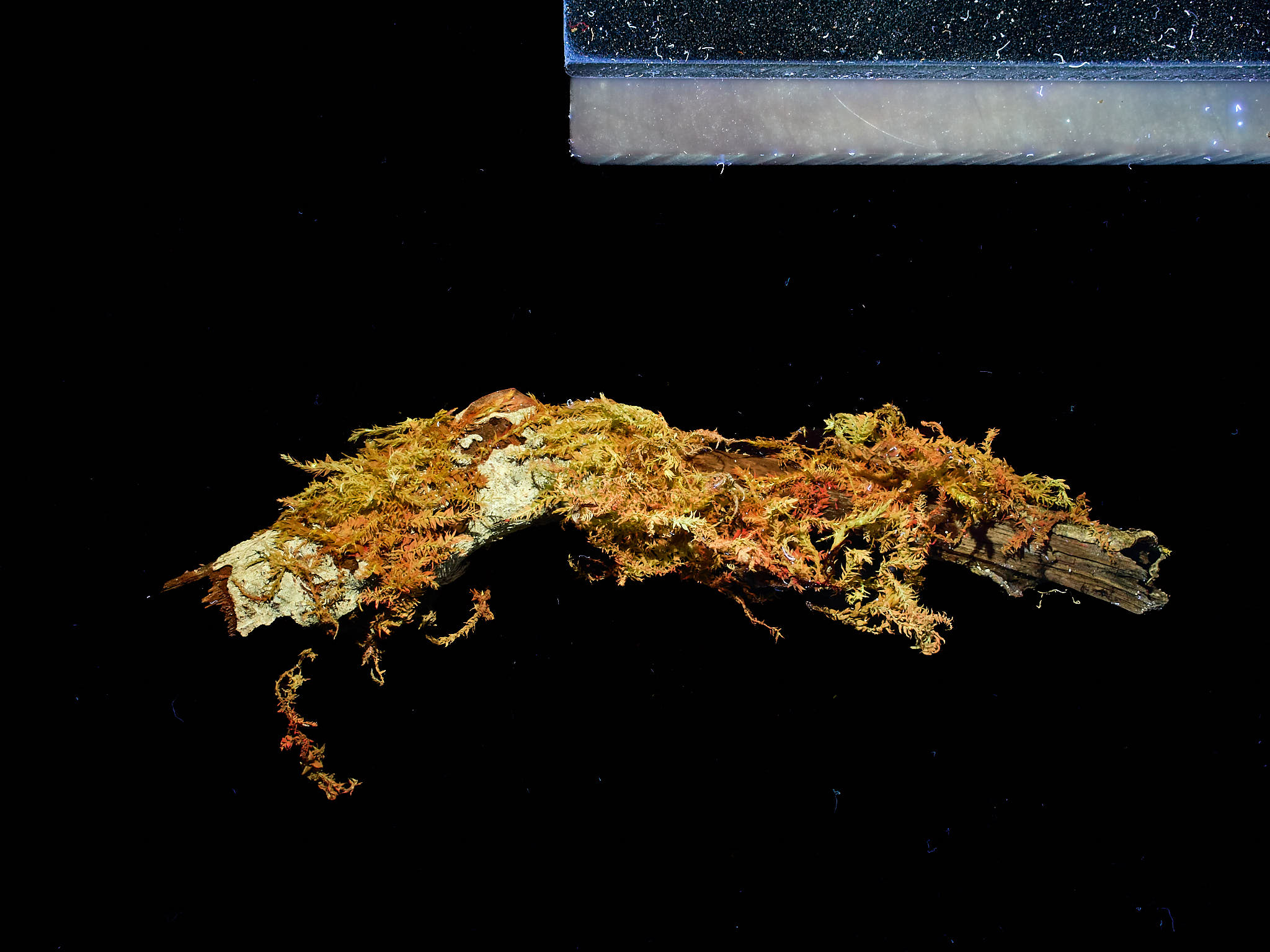
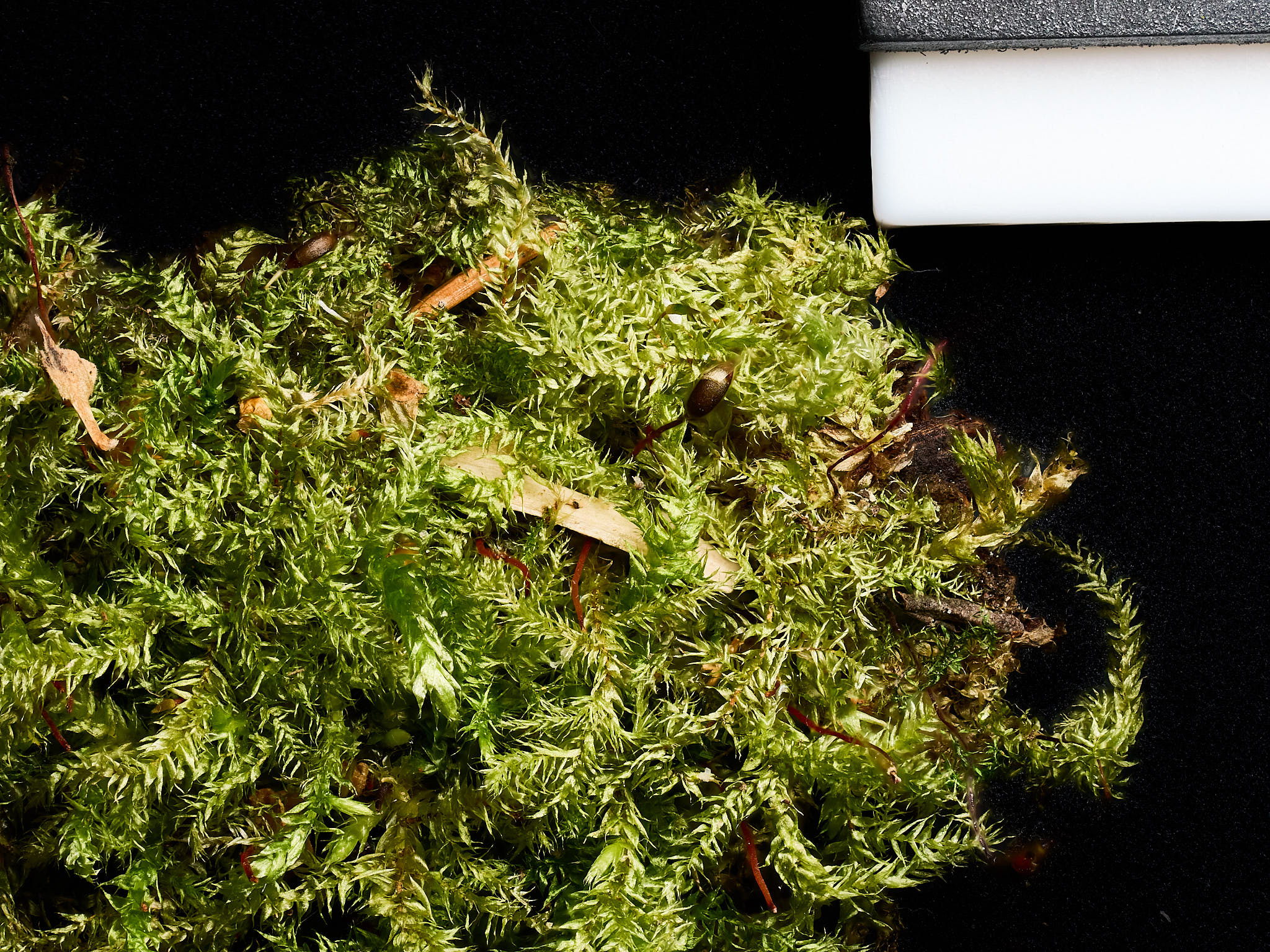
few examples from last night can be seen in [@fig-dead-branches].
::: {#fig-dead-branches layout-ncol="4"}
{fig-alt="Four long-pass glass filters, yellow, orange, red and NIR"
group="branches"}
{fig-alt="Four filters glowing to varying extents."
group="branches"}
{fig-alt="Four filters glowing to varying extents."
group="branches"}
{fig-alt="Four filters glowing to varying extents."
group="branches"}
{fig-alt="Four filters glowing to varying extents."
group="branches"}
{fig-alt="Four filters glowing to varying extents."
group="branches"}
{fig-alt="Four filters glowing to varying extents."
group="branches"}
{fig-alt="Four filters glowing to varying extents."
group="branches"}
{fig-alt="Four filters glowing to varying extents."
group="branches"}
{fig-alt="Four filters glowing to varying extents."
group="branches"}
{fig-alt="Four filters glowing to varying extents."
group="filters"}
{fig-alt="Four filters glowing to varying extents."
group="filters"}
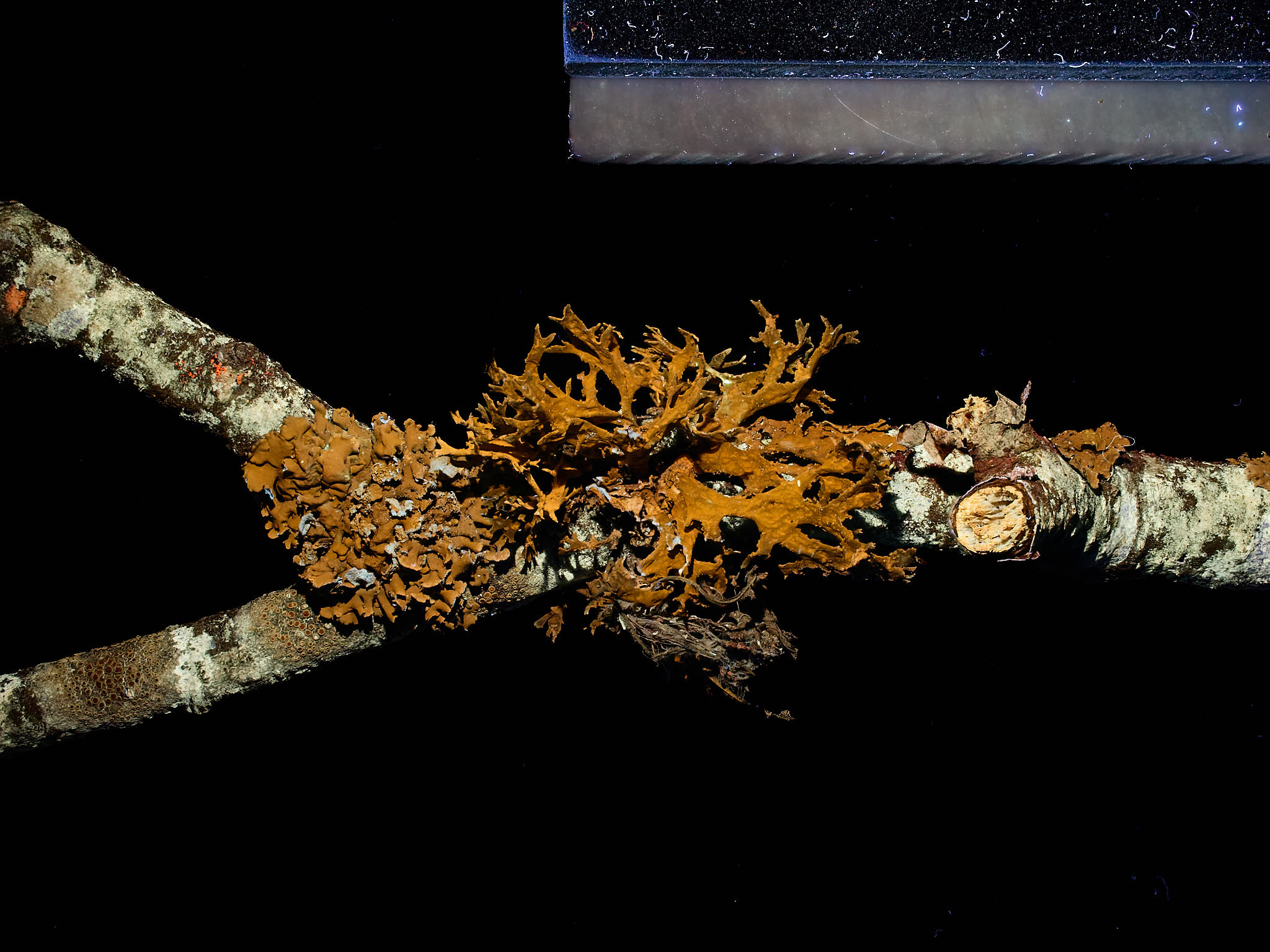
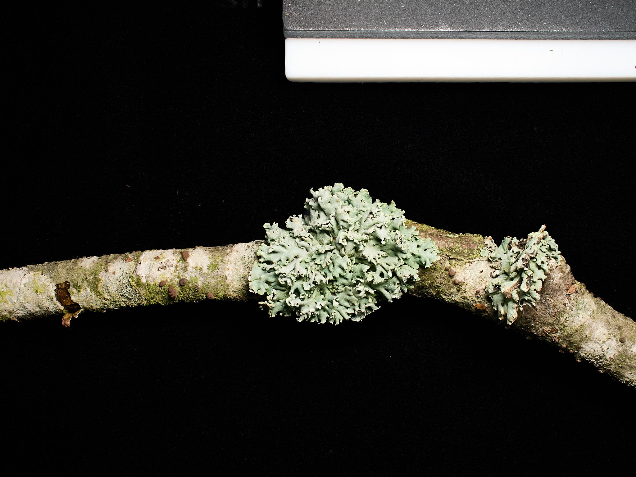
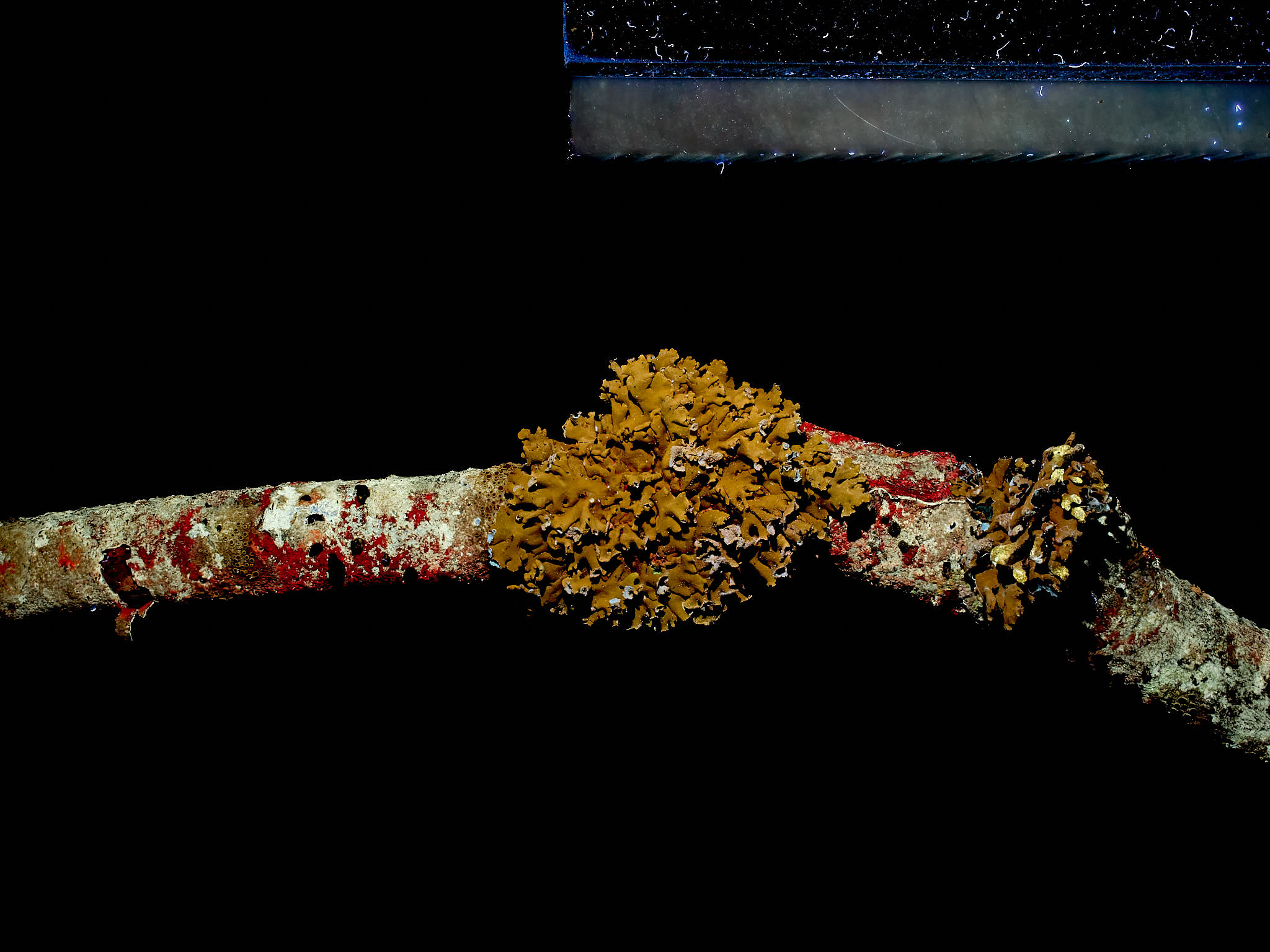
Photographs of four dead tree branches, covered with lichens and mosses.
The background is in all photographs the same black velvet cloth. The
edge of a slab of white PTFE (Teflon) is visible on the top-right corner
of the photographs. In, B, D, F, H, and J the filters used on the camera
lens blocked the UV-A radiation used to excite fluorescence. Light
sources: Sunwayfoto FL96 at 5500K LED fill light and Jaxman Uc1
flashlight. Camera: Olympus OM-1. For visible fluorescence barrier
filter: Firecrest UV400 + Tiffen 2A. Lens: A--J M.Zuiko 25 mm 1:1.2 Pro,
K-L M.Zuiko 90 mm 1:3.5 Macro Pro. Photographs white-balanced and edited
in Capture One Pro version 16.5. Focus-stacks of 20 or 80 photographs
were merged in Helicon Focus 8.2.18 Pro to increase the depth of field.
:::
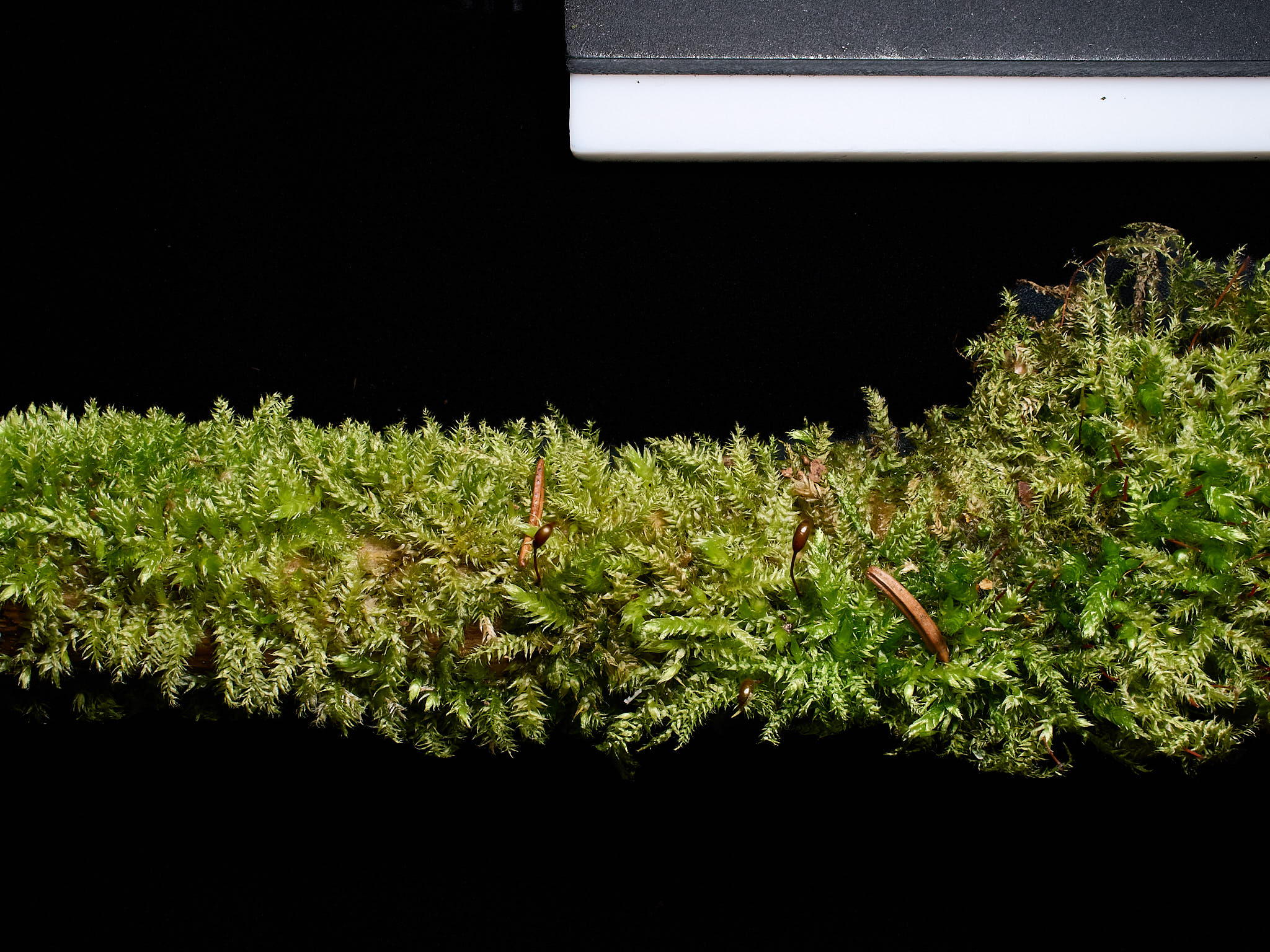
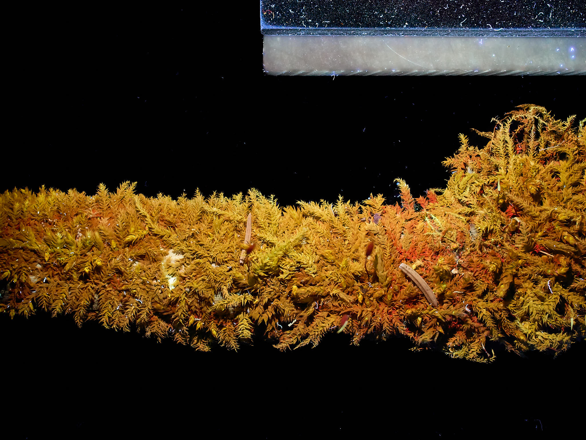
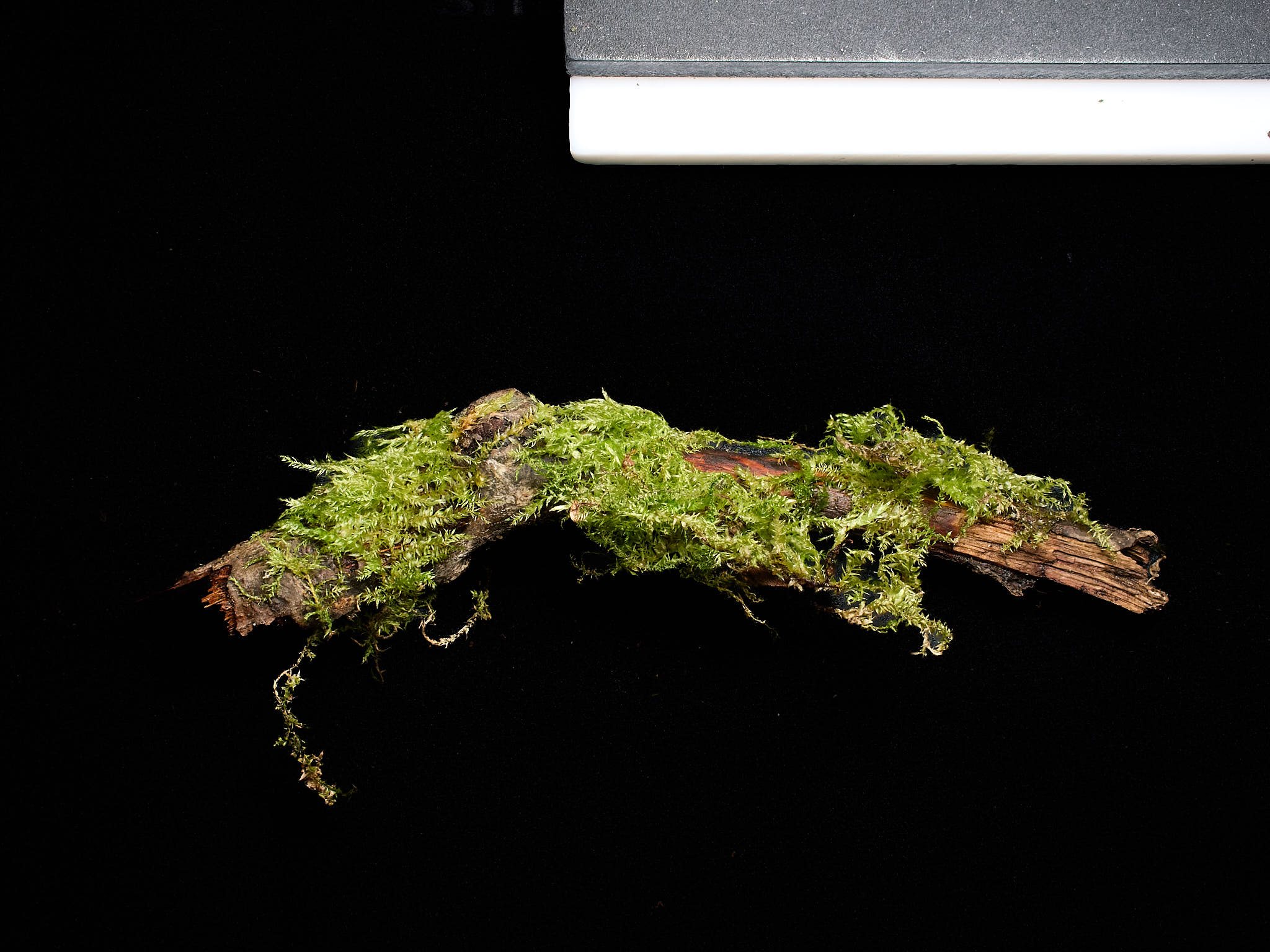
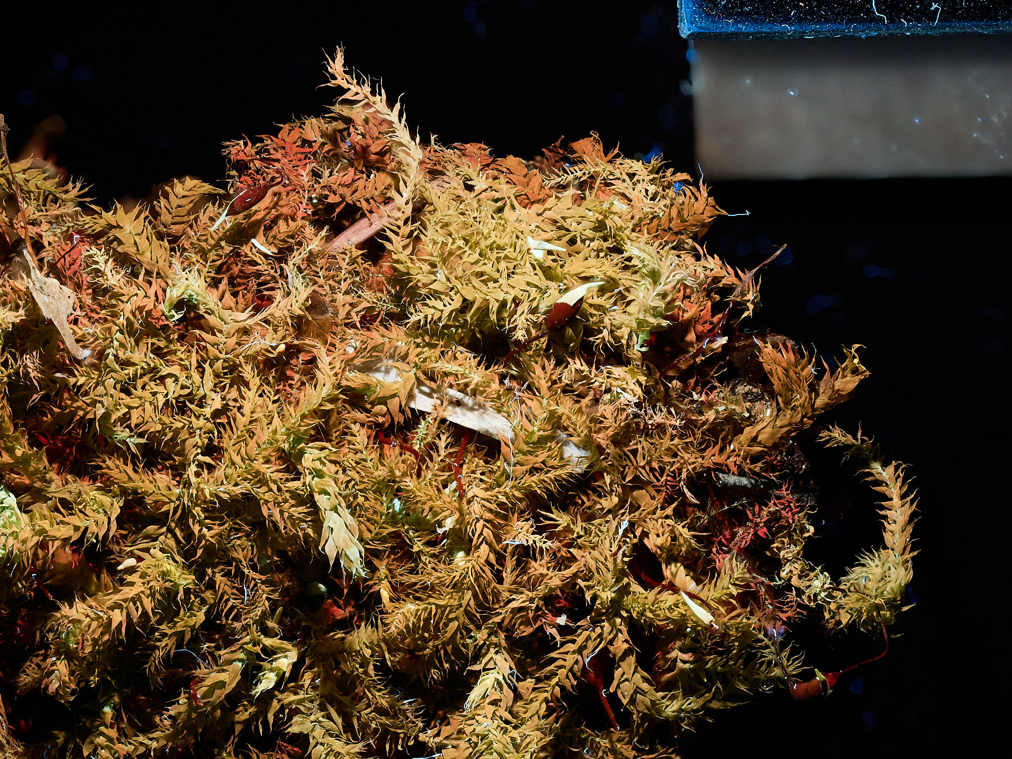
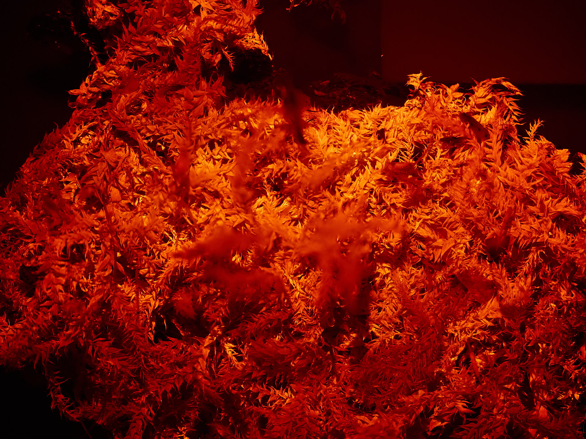
With suitable filters and lenses we can even attempt macro-photography of UV-A-induced chlorophyll fluorescence with a modified mirrorless camera ([@fig-uvinirf]).
::: {#fig-uvinirf layout-ncol="2" width="50%}
{fig-alt="Four long-pass glass filters, yellow, orange, red and NIR"
group="branches"}
{fig-alt="Four filters glowing to varying extents."
group="branches"}
Moss on a dead branch. Illuminated with A: white light or B: UV-A radiation. Only difference with images in [@fig-dead-branches] in the approach was adding a long-pass filter with a cut-in at 650 nm (HB650). Using a filter with cut-in at 695 nm (Heliopan RG695) resulted in a similar image but required a longer exposure time. Camera: full-spectrum converted Olympus E-M1 camera. See legend to [@fig-dead-branches] for other details.
:::
## Conclusion
Photographing UV-A-induced visible fluorescence is interesting and less
demanding in equipment and technique than photography in reflected UV radiation.
An unmodified digital camera can be used and long pass filters are in general
cheaper and more common than UV short-pass filters that block visible and
infrared radiation effectively enough. UV-A as excitation is convenient and easy
to work with, blue light could be used instead if we are interested in
fluorescence at longer wavelengths or for safety reasons in teaching situations.
Using UV-B radiation to induce UV-A and violet fluorescence is in principle
possible but more demanding in practice. Photographing
visible-light induced near infrared fluorescence is more demanding in equipment,
but opens interesting possibilities. Could we with comparatively cheap equipment
use photography to qualitatively assess changes epidermal UV transmittance under
controlled conditions?
## Other sources of information and help
The [_UltravioletPhotography_ discussion group](https://www.ultravioletphotography.com/) is a very friendly and knowledgeable group of people from around the world with an interest in UV, NIR, and UV-induced fluorescence.
The web sites of Adrian Davies, author of three of the books listed below, include galleries of photographs, including some with photographs of UV-A induced fluorescence. See [Imaging the Invisible](https://www.imagingtheinvisible.com/gallery_714121.html) and
[Adrian Davies imaging](https://www.adriandaviesimaging.com).
## Further reading


